About this Blog

This is about the combination of two interests, Radio Control vehicles and Science Fiction models. This blog documents my science fiction spaceship and radio controlled vehicle projects.

Tuesday, 6 February 2018

Reverse Trike Part 1

I have at least 11, if not more, unfinished projects piling up in my shed. A few of them are so very close to being completed. The sensible thing to do would be to finish the nearly done ones off. What a good idea, I'll make it a new years resolution to not start anything new until I have finished at least two of the existing projects...

I started a new project...

I have been playing a little hill climbing style game on my phone called Prime Peaks. One of the vehicles I took a liking to in the game is called the Pealing Pea, it's a little reverse trike. I thought it might be fun to try and make an RC version some day and then I remembered I have a Traxxas Jato chassis with an almost complete set of front end parts lying around in a box, which may be able to be modded to work. I also have a pair of Imex Jumbo maxx Claw Dawgs wheels and tyres, one of which would make a cool big single rear wheel, and I also have a spare 540 motor with gear box sitting around as well.

Here is the first incarnation of the concept I put a couple of those weirdly scaled wrestler figures in some Axial Wraith seats to see how they fit.


I went with a single arm rear suspension made from some rectangular section aluminium. I  hack-sawed and filed a couple of 60 degree v slots along the length and bent the dog leg shape shown. The joins were brazed together with aluminium brazing rod and a propane torch.
The rear shock is a Traxxas GTR shock from a Slayer or Revo or Summit with a Slayer grade spring.
The arm pivots on an 8mm aluminium pin using a couple of 8x16 flanged bearings in the arm itself.
The mount is a piece of aluminium channel with another ali plate brazed on for the shock tower. I drilled a range of holes for shock placement but those GTR shocks are pretty stiff so I found the bottom hole worked best to balance with the front shocks which are stock Jato shocks, the same size as the rear shock just made from plastic. That's one of the things I like about using Traxxas parts for my creations is that the parts interchange fairly easily between models.


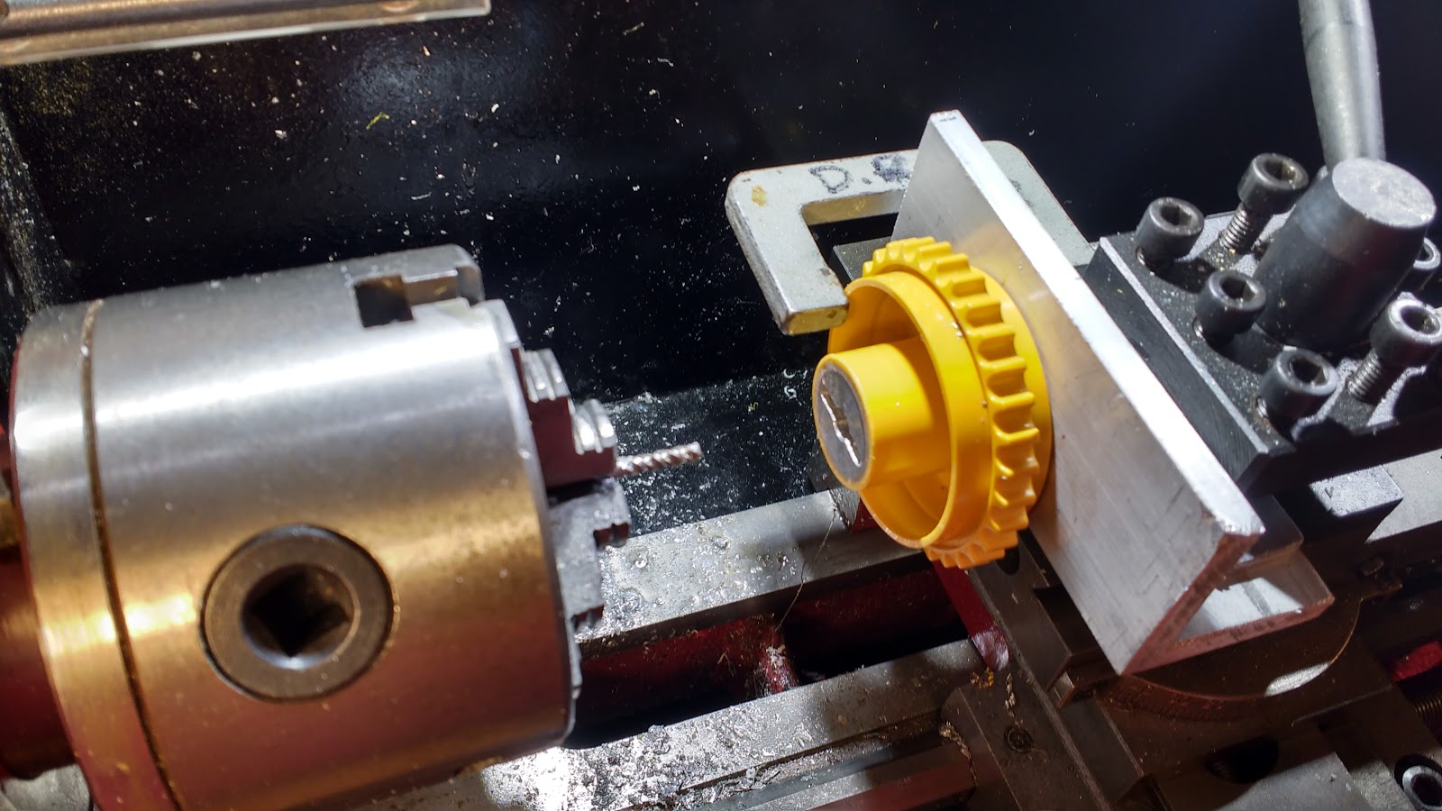
The motor mounts in a radius cut at the end of the arm and is held on with a chopped up hose clamp arrangement. It looks a bit crude but it works. The motor/gearbox combo is rated at 500rpm at 12 volts. It is not particularly heavy duty and after a little test drive all the gearbox retaining screws were found to be loose, I've since locktighted them all. It has only got a plain bearing (not ball) and I am sure it is not designed to take such an axial load, not to mention the hammering it will get if thrashed over jumps an off road tracks. However its what Ive got and it was cheap, only around $15.00 on ebay from China. I am pretty keen on this concept of a motor per wheel, I wish I could find something more robust and flatter that would fit inside the wheel but I suspect that even if such a beast exists it would be way out of my budget.


I came to the conclusion that those pesky wrestler figures just looked too small and the two of them didn't leave enough room for all the electronics and a battery that have to be crammed in there somewhere. So I ditched them in favour of a Tamiya driver figure that I calculate to be 1/8th scale.


As part of the re-arrangement of the driver I decided to flip the side the rear arm was facing. The weight of the motor and gear box tend to roll the vehicle to the side they are on so I thought to counteract that by placing the battery on the opposite side to them. The Jato chassis is asymmetrical in that one side is wider than the other, it is a gas powered car and the widest side is supposed to house the tuned pipe muffler, this is where the battery fitted the best so the arm had to be flipped, all the holes for the hose clamp and shock attachment redone. It wasn't fun flipping the arm, it is quite fiddly to remove and re-insert the pivot pin cause there are a couple of thin spacers made from a thin slice of brass tube that have to line up with the bearings so the pin will go through...aargh. It was a frustrating exercise but worth it as the trike now sits level instead of leaning to the motor side.


The driver figure is held on to a couple of metal standoffs with a couple of M4 screws. Those standoffs are mounted on a PVC false floor I made to give a flat surface to mount everything to. The Jato chassis floor has a lot of lumps and obstructions that got in the way. The false floor is attached to the chassis with 8 M3 counter sunk screws that use a bunch of existing holes that were already in the chassis plus a few extras thrown in for good measure. The underside of the floor is built up from a couple of layers of 3mm and 6mm pvc sheet superglued together. It also blocks some large holes in the Jato blue anodised aluminium chassis. I tried to save some weight but it still ended fairly heavy for what it does,. Grey PVC sheet is a relatively heavy material, but strong and easy to work, it can be drilled tapped, sanded, sawed, heated and bent, takes paint well and superglues extremely well. It cannot however be laser cut as the gases given off will corrode the laser itself and are very toxic.


For testing I used a LRP Runner plus Reverse ESC which is for an old school brushed motor. The ESC, reciever and battery are held down by self adhesive velcro, the standard i use is hooks to chassis and Loops on electronic components.
I cut down the Jato radio tray which locates the steering servo and made a couple of M3 tapped aluminium posts to support the cut end.


Next was the body and I first cut up some cardboard shapes to see how it would all fit before committing to 2mm Foamed PVC sheet. I chose the Foamed PVC sheet as a bit of an experiment to try out the material where before I would have used styrene. The foamed PVC is a bit more flexible than styrene and considerably less brittle though not as surface impact resistant, the surface of the foamed pvc sheet dings easily.


As I mentioned I have done a test drive on 7.4 volts (2S) which is adequate but not particularly fast. It would be pretty quick on a 4S or 14.4 volt battery with a suitable ESC and the motor can take the voltage but I fear the gear box would not be mechanically able to take the extra load for very long. A 3S or 11.1 volts may be the sweet spot for this project but that is a bit further on down the track yet.


More soon...

Monday, 21 August 2017

ToyBash 2 part 2

I installed the nerf guns on the sides.
A piece of 10mm foamed PVC supports the sides of the guns which was perfect as the removal of the handle left precisely a 10mm gap.
A part from the Bruder Dozer that was removed to allow for the motor module to fit was added as a hub detail.
I cut up the hubs from the Wall E truck wheels that originally mounted here and re-used them to mount to the support arms along with a small nylon spacer turned on the mini lathe. They are held on with the original screw so they can be removed for working on and painting.

It looks kinda kooky at the moment, the arms hang down off level which I like, gives it a bit of gunslinger attitude. Hopefully with more detailing and primer it should all come together in the end.
I am thinking about some form of cheap led light chaser effect that would be visible in the long horizontal slot in the "laser rock cutters".


I have also been working on the cabin and adding some bits and pieces to the underside and building up a hood at the front using a couple of bits of an old Zoid toy.
From the side the front now looks a bit like a triceratops which I am quite happy about.
There is still more detailing in this area to go, I am going to add some checkerplate walkwaysalong the side as I have some 1/25 scale checkerplate styrene sheet that I have had for years and never found a use for.


I also hit the back tank section with some red oxide primer to see how its traveling... needs more pipes, probably some single core wire will finish this bit off.


I finally got around to wiring up the motors and testing them by connecting a battery to each one and watching it trundle forward down the hall straight as a die.
It works, as predicted a bit slow on 7.2 volts, but if I can find a pair of forward and reverse brushed motor speed controllers able to take 4s cells otherwise known as 14.4 volts they should be fine. I disconnected one of the batteries to observe the skid steering and it also works well. I suspect the ABS plastic tracks will scratch easily and I am not excited about trying to paint them, I just wish they were made from grey plastic rather than yellow but apparently you can get replacement tracks direct from Bruder in Germany and they do have grey versions but a shorter loop for an excavator model. Might have to get more than one set if these ever get used enough to wear out.

More soon...

Tuesday, 8 August 2017

ToyBash 2 part 1

True to form I started a new project, when I have so many others crying out for completion.

I have had the tracked lower section of the Bruder dozer toy from the original ToyBash truck project lying around without any concept of what to do with it . Very recently I acquired a Wall E Truck toy on ebay and when it arrived in the post I had an idea about combining the two.


But before that I wanted to be see if I could add a drive mechanism to the Bruder tracks so they could be radio controlled. I had a couple of gear motors, another ebay find, which were were very cheap at around $12.00 (including postage from China) and have  really well made metal gears inside a plastic housing. The question was would they fit into the space available in the Bruder chassis at the correct track width. After a bit of measurement it looked like they could be just squeezed in. I built a sturdy mount from aluminium angle and a bit of 3mm sheet and then hacked away at the ABS plastic of the chassis  so the whole unit could be slid into position. Some epoxy putty was slapped into the rear of the chassis and a piece of PVC sheet superglued in to the middle allowing for tapped holes so the mount could be securely bolted in place with m4 cap screws.


At 12 volts with no load they produce  only 70 rpm which may be a bit slow so we will see how that works out in due course.
The Bruder dozer has molded-in fake rollers that the tracks just slide over. I wanted to reduce the friction so I decided to try and modify the track supports and add actual rolling rollers. I hacked away all the bits of ABS that were the non-functioning rollers leaving the support brackets. These were then drilled to take a 2mm piano wire pin cut with a Dremel metal cut of disc. The rollers needed to be 16mm in diameter, I had some 12mm PVC rod and then found some PVC conduit in my stock with a 12mm ID and a 16mm OD, so in my mini lathe I machined up 16 sets of roller parts. I also made the top track return roller using the original molded ABS one I cut off. In the picture below you can see the modified track support above with the un-modified version still with the non-working rollers at the bottom.


I mostly used pair of electronic flush cutting nippers to hack away the unwanted plastic along with a razor saw and much careful sanding and filing. Below is another comparison of before and after on the track supports plus the new rollers and pins.


The separate roller parts were glued together with thin superglue wicked into the join and then once set they were assembled with the pins being retained with another small drop of thin superglue, being careful not to get any on the rollers. The result has been quite successful the tracks now roll smoothly along and the friction has been substantially reduced.


The next drive train job to tackle was the drive sprockets onto the motor gearbox shafts. Conveniently the output shaft on the motors has a M3 tapped hole in the end and a 3mm hole in the shaft to take a pin. I just had to machine a hub with a slot to engage with the pin. I had already made the hubs using some aluminium rod and glued them into the plastic sprocket wheel with thin super glue and baking soda to fill the gaps. It was after this I came up with the idea to mill some pin slots, so I needed a way to hold the sprocket in the tool post of the mini lathe spinning a 3mm endmill in the 3 jaw and use the cross slide to move the workpiece, like a poor mans milling machine.


 I cut a piece of thick aluminium angle and clamped it in the tool post. Then with a 2.5mm drill in the 3 jaw chuck, moved the carriage forward thus drilling a hole at the exact centre height of the chuck. This was then tapped M3 and the sprocket bolted in position through a pre drilled 3mm hole in the hub. The hub also has a 6mm hole that only goes about halfway in which is the size of the output shaft on the gear motor. With a tiny clamp stopping any rotation the slot was gingerly cut from the centre out in both directions a millimeter deep at a time for a total depth of 3mm.
This slot engages with a pin in the shaft locating it radially and axially at the correct track centre distance and the sprocket is retained with a 3mm cap screw into the the threaded portion at the end of the shaft.

Of course it would have been sensible to cut the slot before gluing the hub into the plastic sprocket but when you are working this stuff out as you go along sometimes the penny drops a bit later than would have been ideal.

I have yet to wire up the motors for a preliminary test but so far it all looks like it will work.

Now with all the major mechanical issues addressed what does the vehicle itself look like, well here it is so far...


I was originally thinking of using the Wall E cab but remembered I had a 1/25 scale truck cab lying around which I think looked a lot more interesting when combined with the digging tooth from the Bruder dozer. The cab section is held on with some screws so it can be removed and worked on separately.
Some acrylic plastic wine glasses from a charity shop are being used as tanks at the rear, covered with a plethora of pipes and kit part detailing. The whole rear tank module is removable (held on with a couple of cap screws into some more superglued PVC sheet drilled and tapped M3) so the motor mount can be extracted for servicing if necessary.


I thought the arms at the side of the Wall E truck which held some wacky tractor wheels could be re-purposed for some laser like devices making this some kind of laser mining vehicle. I had a Nerf gun toy that might fit the bill for this and found another one new for only $7.00 at Target for the other side. I removed the handle which is conveniently a separate part.


Various holes in the body have been filled with styrene strip and detailing of the surfaces has begun.


More soon...

Most Popular Posts in the Last 7 Days