About this Blog

This is about the combination of two interests, Radio Control vehicles and Science Fiction models. This blog documents my science fiction spaceship and radio controlled vehicle projects.

Sunday 21 March 2021

Barbie Jet - Freighter Spaceship part 2

The cockpit interior and occupant figures were painted and weathered. The lighting wired up and the whole bridge module was glued into position on the hull with no further interior access possible.


Moving on to the rear of the craft I blocked in the tail section and added all the engine bells. The engine lighting was wired in and tested. Before gluing the side pods in position I sprayed primer grey onto the bits that will be extremely difficult to reach later, mainly the area around the cutaways for the large engine bells and the engine bells themselves.


I am using MR11 LED mini downlight bulbs at 12 volts. All six of them together are drawing around 1 amp. These have a bi-pin ceramic connector which just fits inside a small length of pvc conduit that has been glued into holes at the back of each of the acrylic cups I'm using as engine bells.

The two larger engine bells on the side pods have a plastic tap handle glued inside them. The tap handles have a ribbed interior and a slightly curved hexagonal shape that adds a bit of interesting detail.


I also made up a cargo door that would hinge down to form a loading ramp. In this case it is not operable but doubles as an access hatch to get to the engine lighting connectors. I added a switch so the engine lights can be turned off leaving the cockpit interior lights still on.

Once the dimensions could be ascertained I designed up a door detail on LibreCad, my new free ( open source) 2D CAD program of choice. Making sure to put a dot at the centre of each radius I printed it out fullsize and stuck that template onto a piece of 2mm styrene (HIPS) sheet. Then each dot was drilled out with a step drill to 8mm diameter as the curves were designed with a 4mm radius. Then the lines between each hole were cut and the resulting part after a bit of sanding was stuck to a piece of Evergreen grooved sheet. I made up a chunky looking hinge element that acts as a handle to remove the panel which has a magnetic cupboard catch at the top holding it in place. Looks like I will need one at the bottom as well.


I did test that I could get my hand in to where the lighting connectors were to go before I finalised the size of the access hole and therefore the dimensions of the cargo door. 

I put a 1/72 scale man in the following photo which shows the relative size of the spacecraft.


Returning to the front end I chopped the nose cap in half and fixed it in place with some internal tabs of 2mm styrene with thick superglue and epoxy putty to fill the large gaps. More polyester putty will be needed to fully fair in the shape.


Thanks for looking.

More soon.


Saturday 13 March 2021

Barbie Jet - Freighter Spaceship part 1

In the last post about the completion of the Moon Bug Project, I promised the next project would be to complete the old New Spaceship model, however inspiration struck and I made some progress on another project that has been waiting in the wings for some years. 

I still intend that will be the next project taken to completion will be the old New Spaceship model but I had an idea about how to use the giant pink Barbie Jet plane fuselage that I got from a charity shop many years ago and I just had to see if the idea would work. 


I used the engines  from the Barbie Jet for the Escape Pod Mk2 project back in 2016  and over the ensuing years have been trying to come up with an idea to employ the massive hull shape. Several thumbnails were drawn up, rough CG models built and I filled in the cockpit windows but it never progressed any further as none of the designs floated my boat as it were.

Fusleage with the windows filled in and a rough idea of where the spaceship bridge windows would be in a very early concept, ultimately rejected.


Rejected rough CG model front view.


Upside down fuselage version, also rejected.


A swiveling lifting engine idea, rejected.

Photoshopped lifting engine done over a photo of the fuselage.


More recently I came across an Ian McQue rough drawing on instagram that got me thinking about another way to use the bulky pink jet hull. A couple of thumbnails  and many months later I had enough of a concept to motivate me to start building.

Ian McQue sketch Instagram post, cropped.

Looks like a giant version of the spaceship in Monty Python's Life of Brian, rejected.

Getting there but still not right.

This is the thumbnail that got me started and suggested an approach.


The thumbnail above was the one that got me started as I had an idea to cut the fuselage down the middle and spread it apart at the rear making more of a wedge shape. This I promptly did sawing the fuselage down the centre. I cut the nose cap off and kept that as a whole piece first.

There was still something I still didn't like about this until I wondered what would it be like if the two sides were also tilted in at the top. That idea clinched it for me as I thought it was a much more interesting shape. I attacked the two sides by holding them onto a belt sander until I removed enough styrene material to make them come together at the front so that the nose cap would still sort of fit.


I then set about to make a simple plywood structure that would hold the two sides together at an angle and provide a place to mount the 15mm water pipe mounting pole flanges one top and one bottom. I find this 15mm water pipe to be a really sturdy support for these heavy models it locks in place and is easily removed if needed due to the tapered thread.

 The plastic (styrene) sides were glued to the plywood using super glue and reinforced with a lot of baking soda and thin super glue.


 In the photos above you can also see some 90mm PVC storm water pipe cut in half joined to a fairing made from a plastic measuring spoon also cut in half. These hard plastic spoons are a really useful shape for blisters and fairings and come in a set of four. I have used a number of them on different projects over the years, cutting off the handles and sanding the stub back to the oval shape.


I also rummaged through my stash of acrylic cups to find suitable engine bells and cut down the suitable candidates. I have a set of six Christmas wine glasses made in really thick acrylic that I am thinking of using as the lifting engines as this model is intended to be a lander with a rear cargo door.


I have another four acrylic glasses not shown in the photo which I will add at the rear. The intention is this model is to be liberally festooned with engine bells.

The next part requiring attention was the placement of the bridge/cockpit. I tried a couple of cardboard ideas along the lines of the Ian McQue sketch but it wasn't working. I then had the idea to try another spoon shape and that seemed to work so I taped the spoon to the hull and marked out a horizontal window line with a scribing tool. A piece of 2mm acrylic was heated with a heat gun until soft and pressed into the back of the spoon with a soft cloth to protect my fingers from burning to form the cockpit glass. A slot was then cutout of the spoon to make the window shape. The acrylic was then glued in from behind and a couple of small evergreen strips added as window mullions.


The next step was to build a cockpit interior as it would have to be sealed in without any means of access. Three LEDs were also added to light the cockpit a central white and a red each side for interest. The power supply will be at the usual 12 volts so after consulting an online calculator a 390 ohm resistor was added to the three leds in series at the positive end.

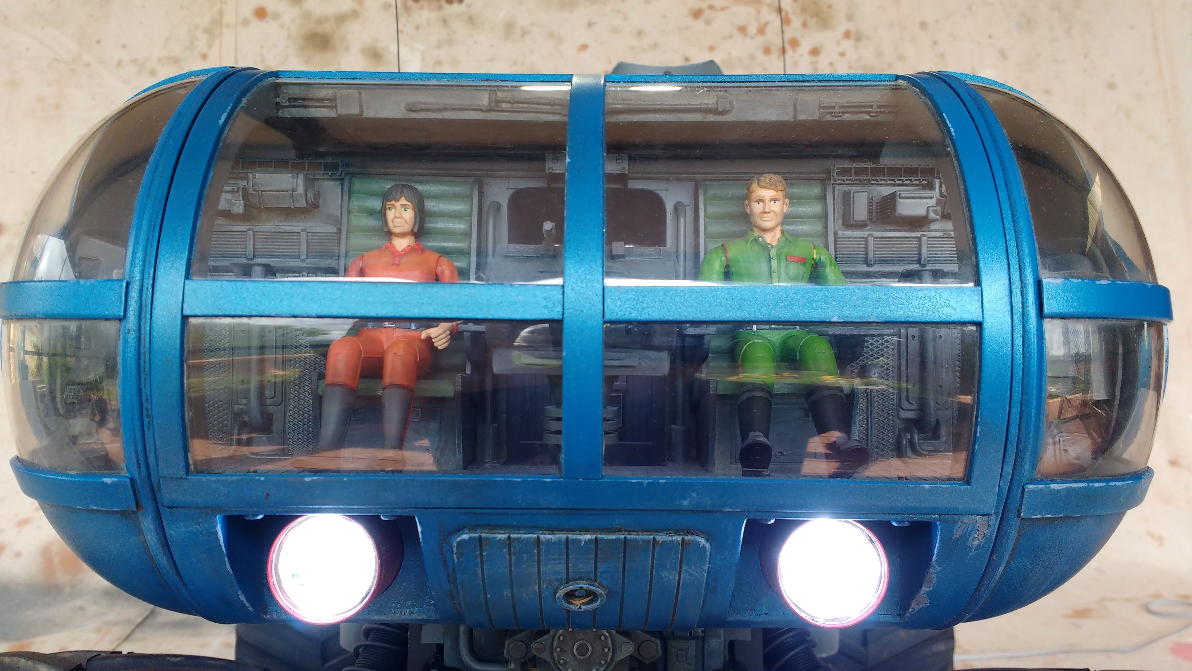
The scale I decided was 1/72 so three figures of that scale were obtained from my figures box and added to the mix. Most of this will hardly be visible through the tiny windows however a curious onlooker ought to be rewarded if they take the trouble to peer inside. The lighting should help to draw any viewer to take a look.

The seated pilots are on a removable base at the moment so I can get easier access for painting the interior. It will have to be finish painted before installation as access will be impossible later.


I have primed the cockpit interior and now need to paint the figures which are so tiny, something I am not looking forward to. I can't bear working on tiny models that's why I generally build so big. In this case even though the model is quite large in volume the scale is small as I am trying to convey the impression of something really huge.

Next up is to sort out the rear end and the arrangement of all the engine nozzles and their associated light sources.

Thanks for looking,

More soon...


Friday 5 March 2021

Moon Bug part 7 - Completed.

 Its been 5 months since the last post on the Moon bug and I have not been able to do any modeling for some time but I have finally managed to finish the Moon Bug project.

Last time the model was at the primer stage, so the first job was to devise a paint scheme. As is my process these days I took a grey primer photo into photoshop and fiddled about until I came up with something I liked.As the vehicle has a whimsical comic book outline I wanted to do a colorful paint job to go with it. This is what I came up with.


 I then decided to design up and make some decals to add to the graphic nature of the finish. These i designed in Inkscape which is a free open source vector graphic editing program. I have always liked the graphic elements that Chriss Foss would apply to his gouache painted spacecraft book covers of the 1970s'. Referring to my Chriss Foss art book I availed myself of some of his genius and some of the decals do bear a very strong resemblance to his work. Here is the decal sheet.

One of the problems with DIY decals is that inkjet printers can't print white so if you want white in your decal you have to use white decal paper. That then means the carrier is white and you have to carefully cut around each decal to remove the extraneous white around the edges. Of course you can use clear decal paper which means you don't have to be as precise when cutting out the decal as the borders will be clear and will not be visible once applied but any white areas on your design will come out clear. If it is a big decal you can paint a white area where you want the white bit to be but for small decals I think it would be too hard to get the white painted areas that accurate.

I printed onto white decal paper and once cutting out the decals and applying them with much setting solution found that little white edges showed up which wasn't exactly what I wanted. I have since found some online tips for using white decal paper, where the edges of the decal should be coloured with a permanent marker to get rid of any white bleed once applied. Too late for me but a good idea for any future project that needs custom decals.

Paint was car paint from touch up spray cans with varying shades mixed up once decanted into airbrush jars and airbrushed on. Weathering was my usual method of a wash of Tamiya flat back diluted in much methylated spirits, wiped off with a metho soaked rag in the direction of the required streaks and drybrushing with white students acrylic. I then also added some oil paint colour modulation and a dirty brown pin wash.

One of the things I tried out on this model was painted panels lined out with a fine permanent marker pen. Models from Terrahawks recently came up for auction with accompanying photos and they had a surface that used a similar technique to very good effect. 

Photographically it seems to work just fine but in person, to the naked eye the conceit is all too obvious. My conclusion is that I prefer to have panels that are in the very least scribed into the surface if not actually separate from the underlying surface and glued on individually. I prefer the way light hits an actual edge with both a highlight on one side and a shadow on the other.

One thing I added to the model was a couple of dummy whip aerials on the top blisters at the rear. They are made from bicycle gear cable with a couple of plastic kits parts for a mount and a termination at the top. They should wave about fairly realistically when the vehicle is in motion.

I also swapped out the Kyosho springs on the shocks for some much stiffer Arrma springs part number AR330417. These are extremely stiff, fit the Mad Crusher shocks and have no trouble holding up the heavy body. If anything they are a little too stiff at 317gf/mm (17.75lb/inch or 3.109 N/mm) or but so far I haven't found any other springs the right length (75mm) and diameter (ID16mm) with a slightly less stiffness rating. The springs came with a chrome finish so I sprayed them matte black to make them a little less obvious.

Finally here is the finished model.


The next project up for completion is going to be a spaceship. In fact it will be one I started way back in 2013 and haven't touched since. Here is the first part of the project from 2013 - New Spaceship Model part 1.

In fact I need to come up with a better name for this spaceship as New Spaceship Model is pretty lame and considering it was started in 2013 it isn't all that new any more. If you have any suggestions for a decent name for the project please leave a comment.

Thanks for looking...

More soon...


Most Popular Posts in the Last 7 Days