Designing, scratchbuilding and kitbashing Sci fi Spaceships and radio controlled vehicles.
About this Blog
This is about the combination of two interests, Radio Control vehicles and Science Fiction models. This blog documents my science fiction spaceship and radio controlled vehicle projects.
Trawling through my stash for suitable parts I dug out a bulldozer blade from a Bruder toy. I removed the front part of the blade and thought the back part would be good for the rear of the chassis. It needed a section to be removed from the middle to fit. The two abs halves had all the holes filled with scrap sheet abs and some strips to reinforce the join.
This was superglued to the black foamed PVC chassis . While at the rear end I decided to add some chunky detail to the body.
Two tanks were made from PVC pipe caps with a clear centre box from a broken coffee machine. The teal pipes are from a toy that I discovered on a Jason Jensen Trains sci-fi modeling you tube video. Either side are some reels from an old VHS video tape. There is a further layer of finer detailing to go yet.
Moving round the front I made a couple of transitional boxes from styrene sheet. I also made the base for a communications dish.
Next I thought about an entry door. I have a few round surrounds from battery lights I thought might work as I have used these before. I used an online calculator to print out a template to cut out a fishmouth shape from 1mm styrene sheet to mate with the curve of the hull in the same way as on the Moon Bus project.
After thinking about how much space a sliding door would require I decided to split this housing and widen it into an oval shape. I then drew up a door design in CAD and printed it out fullsize on paper. This was then stuck onto two layers of 2mm styrene stuck together with double sided tape. I could then cut out two doors at once.
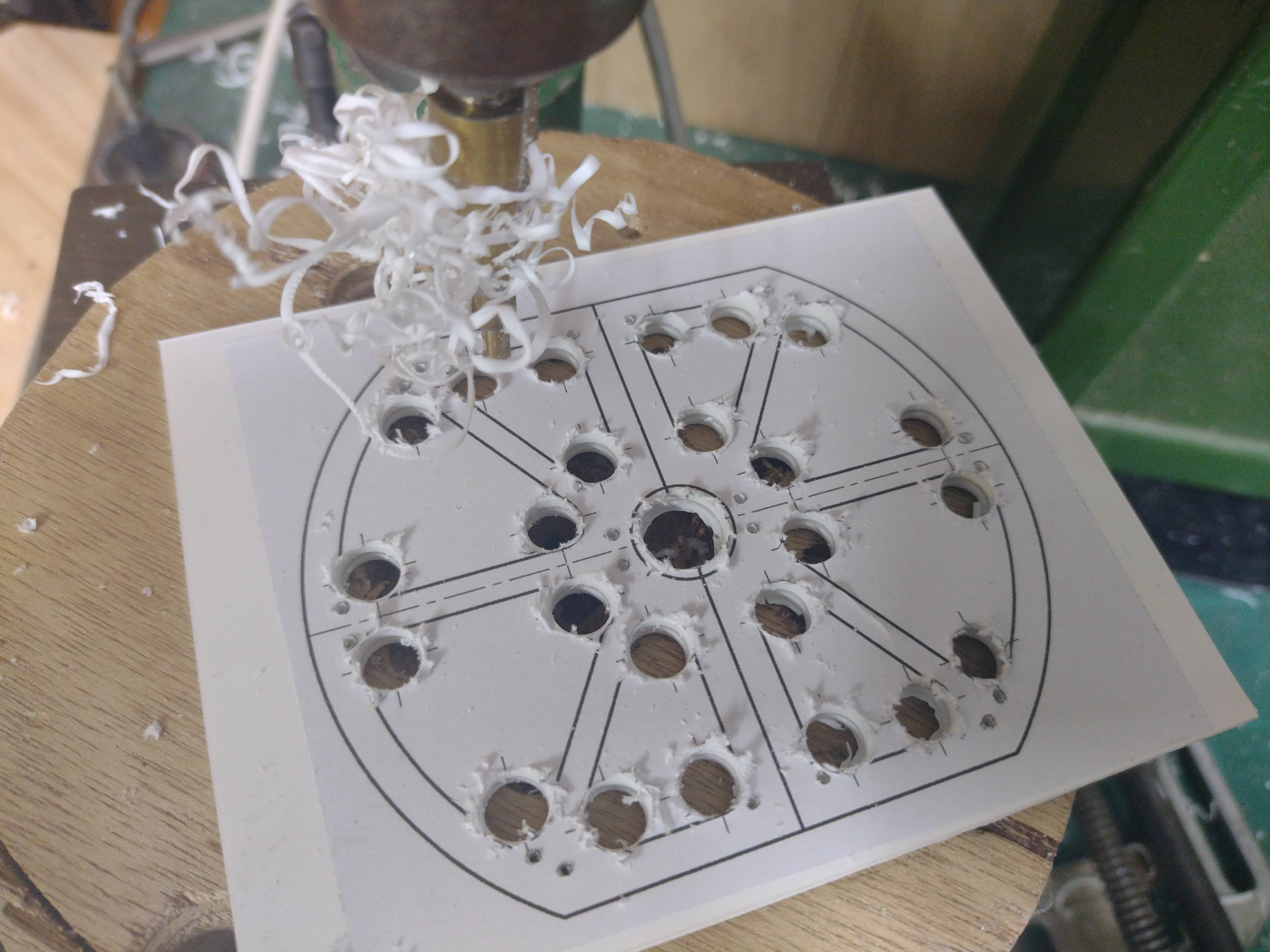
Pilot holes were drilled at the radius centres of all the corners and then drilled out to 8mm with a step drill.
Then using a scroll saw all the little segments were cut out. Careful sanding and filing follows to clean up all the edges and then these filigreed panels are stuck to a backing panel of styrene.
Surround panels were made with some evergreen strips to provide some thickness with the door behind.
These are then glued into the previously split surrounds with more styrene to fill in the missing parts of the door surround. A sheet of wet and dry sand paper is taped to the hull and a final sanding to match the hull shape is done before super gluing the door assemblies to the hull. Any gaps are dealt with with baking soda and thin super glue.
An exhaust vent has also been added made from an angled hair cutting comb with a styrene duct.
Detailing has also started on the top surface. I found a couple of plastic rulers and glued them on as well as a dome shaped lens cover from a video projector. The grey parts are from a 1/35 scale German railway gun kit.
I also added a couple of rabbit ear antennas I had made for a previous project but did not end up using. They are on a sprung pivot so they will hopefully bounce back and forward when traveling. The spring system was taken from the switch of rubbish truck toys.
The last time I posted about this project was in 2017.
With the Science Vessel project nearing completion I was thinking about
which project to work on next. I thought it was high time this project
was brought to completion.
This RC vehicle project has been through a number of design revisions over its life with the current design being the third (and final) body with two previous designs having been started to be built and then rejected.
In the last post I mentioned I was making a wooden buck to form a perspex window over for the front of the vehicle. That was done not long after the 2017 post and the project has sat around dormant since then.
Below you can see the wooden buck I made to heat bend the perspex windscreen. The buck and the perspex piece is made over size to be trimmed back to fit after bending. The trick to heat bending perspex neatly is to only heat the area to be bent. I use bits of thin sheet metal and you could use aluminium foil to mask the hot air from the heat gun off the bits I am keeping flat.
The first process was to apply the gentle curve to the front face of the
window area. I heated the whole section masking off the sides until it
was just slightly soft and used a cotton rag to press it down onto the
former. Once cooled I used the sheet metal masking to just reveal a
roughly 6mm wide strip for the corner bend. That exposed strip was
heated and then bent using a flat piece of wood to push the perspex
against the side of the former. This was then repeated for the other
side. Once cooled it was trimmed to fit the front of the model and 2mm
styrene pieces added. The picture below shows the result. The perspex protective film which was a plastic film was still on the undersurface. If the perspex had a paper protective layer I would have removed it first as it does not stretch like the plastic film does.
There is not much left to do to it other than wire up and install all the various light systems and complete all the surface paneling, and paint it and the figures etc etc. Actually it seems there is still a fair bit to do and it always takes longer than I estimate.
In an attempt to lighten the very heavy body I hacked away at most of the interior bulkheads made from 6mm foamed PVC. This actually did result in a reasonable weight saving.
When I made the chassis originally I had provided a 6v power supply for any future lighting but as I now prefer to run all the lighting at 12 volts I replaced the 6 volt UBEC with a Matek booster board which has an adjustable output voltage. It takes a feed from the 7.2 volt LIPO battery for the vehicles brushed motor and ESC and boosts it to an adjustable voltage in this case adjusted to 12 volts. In order to get a higher voltage than the source you must sacrifice some current but as I am only powering some LEDs which only use a small amount of current there is no problem.
The 12 volts from the Booster Board then goes through a Pololu switch that plugs into the third channel of the receiver to remotely switch the lighting on and off via the push button on the transmitter.
In the photo above you can also see the sway bar arm on the middle axle. It is made from a length of solid brass on each side attached to the axle with a short linkage made from Traxxas rod ends. The bars at the other end are attached using a cap screw clamp to a length of piano wire with a flat ground on each end. A small aluminium spacer spaces the bar out from the chassis plates.
The control console is made from a 1/35 tank hull part with a perspex screen covered in a piece of black 0.5mm styrene with two video screen holes cut into it as well as a series of 1mm holes to look like buttons or indicator lights. Buried inside are 4 bright white leds in series, each dropping 3 volts making 12 volts in total. The occupants of the cabin are a couple of Bruder 1/16 scale figures.
The photo below with a view down through the removable access hatch in the cabin roof shows the console in position.
All the lighting in the following photos are coming from the LEDS inside the console. The glowing edge is the raw edge of the perspex screen. I kinda like its effect so I may not paint over it.
I had an idea to make some sort of glowing revolving tech in a circular area on top of the roof that was yet to be detailed. I had a bunch of cheap LED linear sequencing kits from another project and thought I might be able to adapt one to make leds sequence in a circle making a sort of rotating effect. The leds are white but there are some portholes painted with Tamiya
clear blue which I added to the the Pilgrim Explorer kit part I used
which happily matches the diameter of the existing round shape on the
roof.
The snag with this system is that it runs on 5 volts and not the 12volts I have for the rest of the lighting. I may have to re-employ that UBEC switched to 5v to power this device or use another board to drop the 12 volts down to 5 on the body. That may not be the most efficient way to do it, I'll have to experiment to see if that will work.
You can see the rotating effect in the short video below.
I also made a communications array from some kit parts. The horizontal scanner is a part I was given some years ago. I think it is probably a Millennium Falcon engine part from one of those tiny Bandai kits. It also has the end of a disposable razor, a component I like to add to model somewhere, if at all possible.
The next task is to add some rear lights and then to complete paneling the surface.
I had a bit of a disaster in the painting process which is something I always dread.
The big problem was the paint, top coat and primer just came straight off the black styrene as soon as any masking tape even low-tack got anywhere near it. It flaked off in sheets. It was very depressing.
It all had to be scraped off where the masking was eventually going to be placed, to be re-primed and top coated. Strangely the dodgy primer stuck much better to the parts made from white styrene like the evergreen textured sheet, though small bits were still pulled off with any masking tape application. In these areas I did what I usually do and applied some hair dryer heat to the masking tape as I removed it which aids in softening the gum and preventing small chips coming off.
I did a bit of research to try and figure out why this occurred as it has happened to me randomly in the past. Sometimes the primer is absolutely perfectly fine and very occasionally I find it comes away with the masking. I found a very useful bit of information on you tube about the types of primer I usually use, namely car primer in an aerosol can.
Turns out there are two types available to me locally one good and one bad and I had three cans with both types represented. I sprayed the three different cans I had in sections over some black styrene and after it had dried applied some masking tape. Pulling the masking tape away was extremely revealing. The primer I had used came completely off and the other two had remained intact. The picture below shows the three cans I tested.
The can on the left was the one I used on this model which failed miserably. The other two behaved as one would hope, they stayed on the surface. It turns out the cans that say Multi Surface work very well on plastic, they even state they work on fibreglass on the back. The one that is labelled acrylic primer appears to be absolutely useless on plastic and therefore I will not use it ever again.
Before this all happened I had decided on a predominantly white finish with some sort of red stripes to match the red on the chassis. Below is the model with the base colour applied which I took into photoshop and tried out a number of various versions of red accents finally deciding on the colour rough shown in the second picture which helped to highlight the shape left between the panels that flow around the windows.
This red motif was then masked up extremely gingerly and sprayed with a small can of Ford Blaze red. The white was actually a warm off white called Antarctic white. Once that was done I re-evaluated the front end and decided that maybe the front panel needed some colour as well. So back to photoshop just to check and the colour rough that resulted shown in the second photo below was more to my liking.
My old weathering technique using a mix of Tamiya flat black and ethanol ( methylated spirits) as a dirty wash was employed. The surface is then cleaned off using a rag damp with ethanol leaving the grunge in the crevices. Dry brushing with a light grey students acrylic followed. Detailed scrapes were painted with acrylic hobby paints, a light grey surround with a dark grey core.
Another of the painting tasks was to paint the occupant figures, something I am pretty terrible at. In an attempt to try and improve in this area I watched a lot of You tube videos on figure painting in acrylics. Below is the result, still pretty poor but a lot better than my previous attempts.
The figures were superglued into their seats and the front panel screwed into position. To hide the screw heads I found a piece of red self adhesive vinyl and punched out some small circles that were pretty much the same diameter as the screw holes. The colour is not an exact match but I think it will do the job. I also used a few pieces of the red vinyl in other places on the model.
The solar panel cells on top were picked out with random squares in three shades of grey.
Finally here is the completed model.
Part 1 of this project was way back in October 2014. Part 2, 3 and 4 was a year later in October 2015. Then nothing until 2020. This project has been spread over nearly 6 years so it is satisfying to finally bring it to completion. It's also the third completed model for 2020 which as we all know has been and continues to be a very unusual and challenging year.