To test out my idea of one geared motor per wheel in a spin steer vehicle I built a quick chassis out of wood.
The purpose was to test whether the speed controllers ( dual Traxxas EVX) could handle the load and if the gear ratio was suitable for different sized tyres.
The motors are the cheapest I could find on ebay from China. They are brushed 12 volt 540 can motors with an inline gearbox supposed to run at 500 rpm unloaded. The output shaft is 6mm and runs on a plain bearing.
I had previously estimated that 400 rpm would be about the right top speed required by bolting a wheel to my cordless drill which has a 2 speed gearbox. The lowest speed is 400 rpm and that seemed about right as i ran it along the ground. I decided that perhaps a bit extra might be required so I purchased the 500 rpm units.
There is no suspension at all, with each motor /gearbox unit strapped into some circular holes in the frame.
Each EVX controller is hooked up to the three motors per side in parallel.
One of the controllers has its red wire removed from the receiver plug so only one BEC is being fed to the receiver.
I had already tested the current draw of the motors which is less than 2 amps no load and just over 4 amps loaded, so the EVX speed controllers should be more than capable of handling at least 4 of these motor/gearboxes.
I first tested a set of Axial oversized beadlock wheels (3.8) with Losi ATX 420 tyres, followed by Imex Jumbo Maxx Chevrons which are a slightly smaller circumference. I then bolted on some massive RC4WD Interco Super Swamper 40 series TSL/Bogger scale tyres mounted to my homemade PVC wheels, click the link to read the post- Giant-tyres-and-pvc-wheels
I used my Turnigy 9X radio that I modified to have a return spring on both sticks. Push both sticks forward for straight running. To turn you pull one stick back to brake that side. The EVX speed controllers have a brake system so the stick has to be brought back to brake, then returned to neutral and brought back again to get reverse. This is not ideal, instant reverse would be preferable ( at the cost of potentially tearing up the gearbox) but despite this it does work and you get used to controlling it this way. A gentle tap on the brake on one side gives you a gentle turn. Further manipulation of the sticks allows the full spin steer where one side is in forward and the other reverse spinning the vehicle on the spot.
I also added a Life battery and added a Smarty Pants board to replace the firmware with Open TX.
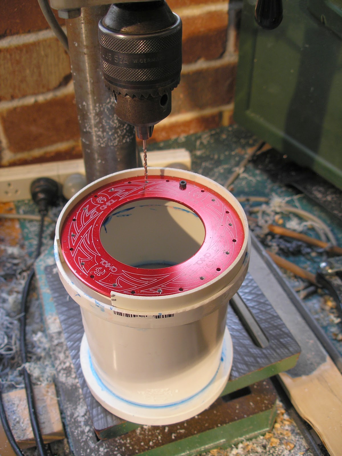
The losi ATX 420 tyres mounted to Axial Oversized beadlocks required some grinding of the bead to fit well. The Axial beadlocks have a wedge shaped receptacle for the bead whereas the tyres have a rectangular bead. The inner edge needs to be chamfered. A sanding drum in the drill press did the trick.
I like these tyres, they are relatively cheap, grippy, seem to be able to cope with on and off road and make a great tyre squeal sound when rubbed along the floor. As a bonus they look very SCI FI.
The Imex Jumbo Maxx wheels were attached to the 6mm gearbox shafts with some modified 14mm hex wheel wideners. I tapped the hole for the axle pin for a M4 grub screw. I wish I could find shorter versions as they really dont need to stick out so far, in fact there would be less sideways load on the plaiin bearing if it wasnt so long.
The Axial beadlocks were attached with some modified Traxxas 17mm hexes which were drilled out 6mm for their whole length to fit over the shafts. This is much better as it is close to the bearing.
A ball bearing supported shaft would be much better mechanically here, but a quantity of quality motors and gearboxes is way outside my budget.
The Bogger/PVC wheels used the same Traxxas 17mm hexes.
Here you can see the Losi 420 tyres against the Boggers. I still cant get over how bloody enormous they are. They are also very a very heavy mass to rotate.
The Losi 420 tyres have a circumference of 564mm whereas the Boggers are 793mm, that is 1.4 times more. It means that the gearbox should be geared down by that amount. I figured that 500 rpm probably would be a poor match for these wheels.
The results of testing showed that for the Imex Jumbo maxx and the Losi 420 tyres 500 rpm gearbox is about correct for a bashing style of driving. I think my first estimate of 400rpm would be better for a more controlled style that I am after for these SCI FI vehicles which are not really about speed. Even with these 500 rpm gearboxes the speed controllers and the motors barely got warm, so I have no fears about adding and extra motor per side for an 8X8.
With the Boggers the motors did manage to turn the wheels but, as predicted, the motors got very hot quickly. If 400 rpm suits the 420 tyres then 0.7 times 400 which is 280 rpm should suit the Boggers.
You can get 200 rpm or 300rpm gearboxes so depending on whether you choose speed or torque you could go either way.
I will probably go 200 rpm as I'm after climbing ability over speed.
Given that I have the 500rpm motors I will use them for a 6X6 I have planned and have a couple of spares.
More soon...
About this Blog
This is about the combination of two interests, Radio Control vehicles and Science Fiction models. This blog documents my science fiction spaceship and radio controlled vehicle projects.
Showing posts with label 40 series. Show all posts
Tuesday, 18 August 2015
Monday, 18 May 2015
Giant Tyres and DIY PVC wheels
So the only alternative was to see if I could make some rims. I had done an experiment in making rims out of PVC plumbing fittings before. In this case it was to fit some Imex 2.8 tyres. I found it was impossible to locate any 2.8 rims any more as they seem to have completely gone out of fashion. After wandering about the hardware store measuring various parts I found some 75mm storm pipe couplings that fit the inner diameter of the 2.8 tyres. They had a convenient lip in the center of the coupler that I could glue a disc hub to that would be square to the wheel. They were trimmed to the right width from one side to achieve the desired offset, meaning that the disc is offset so the suspension arms will not bind especially when turning the front wheels.
I then needed some rings to glue around the edge for a lip that the tyre seats against. I lucked upon some other fittings that had the right ID that could be cut up to produce the rings.
I made the hubs from discs of 6mm grey PVC. These were cut on the drill press using a circle cutting tool. You can see a picture of this in the previous post, tools-part2
I added a bunch of holes and an array of old 1/8th whitworth stainless cap screws I had lying around (as I havn't used imperial fasteners for many many years) for decoration.
After this experiment I wondered if I could get lucky again and find something that would work for the massive RC4WD series 40 tyres. In the pics below you can see them on the left compared with Proline trencher series 40 tyres in the middle and Imex Jumbo Maxx Swamp Dawg tyres on the right, tyres I used to think were huge. In my test of the Axial beadlocks I determined that at least the beadlock rings fit correctly and that as these are available (though discontinued by Axial) I can employ these and try to make a beadlock rim.
A trip back to the hardware store with a vernier caliper to test out any fittings that might do the job. And as it happened I got lucky again and found a fitting that had a built in bead receptacle. Its a 100mm to 90 mm storm pipe reducer. It has an inner lip to seat the 90mm pipe and an outer lip to seat the 100mm pipe that I had to remove with a ball-bearing guided flush edge routing bit mounted in my Makita laminate trimmer (like a small router).
In the photos below you can see the parts that go together to make the rim of one wheel. There is two of the 100/90 reducers, a 90mm coupler, two pieces of 90mm pipe one short and one long and two rings of 90mm pipe split with a small piece removed from the circumference.
There is also a disc of 6mm PVC and a hex made the same way as before.
The two pieces of PVC pipe are glued into the the reducers and seated against the inner lip. The coupler is then glued over the long pipe that so that it seated against the reducer. The disc is then glued in so that it seats against the long tube. The short tube assembly is then glued so that it seats against the disc. It was pure luck that the couplers were exactly the right length required to space the reducers apart to suit the tyres.
Finally after the glue has dried the inner and outer rim is trimmed to the correct length using a Dremel cutter mounted in the drill press. The outer rim needed to be 2mm shorter than the inner rim to allow for the way the bead on the tyre sits. The depth of the bead receptacle is about 1mm shorter than the depth of the bead so that the tyre bead gets compressed by the beadlock ring as it is tightened down. Finally the rings are glued on the inside of the inner rim to thicken up that area to receive the holes for the M2.5 cap screws I decided to use to secure the beadlock rings. After the rings glue is dry the rims got a final pass with the Dremel cutter.
This process require that the two lengths of 90mm tubing are cut precisely to length and square. Now I used my bandsaw to cut them and although the bandsaw was set up and checked with a set square the cuts still are still not totally accurate. This means that the hubs are slightly out of true and this eventuates in a slight wobble on the axle. Some came out pretty square but a couple were a bit off. With a big lathe you could get these totally on the money ('course with a big lathe you could machine a set of funky beadlocks out of solid), however in my situation, with out a well equipped machine shop it is possible to make something that works and I am not going to be spinning these wheels with a high rpm so I think I will get away with it.
The next task was to redrill the Axial beadlock rings. The pitch circle of my PVC rims is not exactly the same as the Axial ones so I made a jig to drill new 2.5mm holes in the rings. I could only get 3 pairs of the same couloured rings and one pair of those is the skulls design whereas the others are the Tribal design (which I prefer). For the inner rings I used the plain ones from the 3 pairs of Axial beadlocks rims I purchased originally and then managed to fine three pairs of green Holey Roller design rings to replace the ones I hijacked ( for a future project).
The jig was a scrap of plywood with a disc of 2mm high impact Styrene (HIPS) cut to the inner diameter of the ring and clamped to the drill table. I drilled a 2mm hole to line up with the original hole in the ring and used a 2mm drill as a locator pin. A new hole was drilled between the existing and on a slightly shorter pitch diameter. then the pin was removed the disc rotated and the pin put back in, thus the old original holes acted as the guide for the new ones. The inner rings were done the same way using another jig with a bigger diameter plastic disc to suit.
A re-drilled ring was then used to drill the 2mm holes in the rims. A split piece of 90mm pipe was used to center the beadlock ring on the hub. The first hole was drilled and a cap screw put in to stop from rotating as the rest of the holes were drilled. I did not tap the holes for the m2.5 thread in the rims, the cap screws can cut their own thread as they are wound in. It makes for a tighter fit and the PVC is flexible enough to cope.
For the 6 wheels I need 144 m2.5 cap screws. I ordered a box of 100 m2.5 X 10 cap screws thinking I only needed 72 of them, I forgot about the inner rings. In case I needed slightly longer screws, I also ordered a box of 100 12mm long cap screws. The box of 100 10mm screws cost me $9.90, the box of 100 12mm screws which I didn't question at the time of ordering arrived with a price of $46.00. When I asked about this they said it was because 12mm is not the common size, huh? I need to get another box of the 10mm screws to complete the task. I can say that after putting three of the tyres on the rims my wrist was sore from all the screwing in and I had a blister on the palm of my hand from pressing on the handle of the allen wrench.
You may notice that the rims are painted yellow. I used a spray can of the typical rust guard epoxy paint. That paint sticks very well to PVC as well as aluminium without flaking off. It needs a day between thin coats, I needed three coats here, so its a slow process. Why yellow? well I stumbled across some concept art, in my searches for futuristic vehicles, that really caught my eye and these tyres will be used for a project that will be very close to the original concept, not a replica but as usual, my take on it.
More soon.
Labels:
2.8,
40 series,
DIY wheels,
Imex,
Interco,
PVC,
RC4WD,
Super Swamper,
Tyres
Monday, 14 January 2013
Explorer
I'm ashamed to say it's been over a year since my last post. My modelling is usually in binges, in other words I do nothing else for a while until I hit a technical or design snag or lack of funds, then leave it alone. In the intervening time I have been learning about and building a couple of valve guitar amps and I'm halfway into a wooden sailboat build. Eventually I get my modelling mojo back and dive back in.
So I now present... a totally new project, the Explorer. It's some sort of mobile planetary exploration vehicle, a travelling laboratory and living quarters. It is based on Traxxas Summit running gear mounted on an extended Revo 3.3 chassis. The inspiration has come from "Snow Cruiser" an Antarctic explorer built in 1939.
Snow Cruiser was a roving base for a crew of 5, consisting of four 10 foot
high electrically powered and individually steerable wheels. It housed
two 150 hp diesel generators to power the electric wheel motors, as well
as living quarters, kitchen,machine shop, photo lab, communications and
storage for a years supply of food.
Yes, I know I haven't finished any of the other projects yet, don't worry I will get back to them, eventually.
All the parts were sourced from the usual place Ebay, from the many RC parts-stripping vendors who buy new kits, and break the model down into components to sell off cheaper than the pre-packaged spare parts.
I've got an older EVX2 speed control which doesn't have low voltage cutoff so I have added a Novak 2C Smart stop unit. The Summit uses two battery packs which connect in series internal to the ESC. The smart stop is wired in with one of the ESC's battery connectors, the side which provides the BEC. It means that only one of the packs is being monitored by the Smart stop, but you can assume the other pack is discharging a similar rate. Here is an extremely helpful wiring diagram courtesy of SuicideNeil from robotwars.00server.com.
Note that the two Titan 550's are replaced with a single Titan 750 in this application. The E Revo uses a pair of standard motors whereas the Summit uses the one larger donk. The new version of the Smart Stop is self sensing so it can cope with 2c-4c packs. There is a pile of much cheaper alternatives from Hobby King which plug directly into the balance lead of the pack which is pretty simple and convenient.
This larger motor is the same size as used in many cordless drills, I have one out of an old Panasonic drill which even has a 32 pitch pinion gear mounted which mates happily with the Summit transmission.
Two aluminium angle battery trays have been attached with my usual aluminium brazing rods.
There is still some work to do on the chassis, bracing the battery trays and a micro servo mount for Hi-Lo gear changing duties. One of the other features of the Summit is remote diff locking, at this stage I think I will just leave that as a manual switch rather than getting the push rod runs sorted out for servos.
I will also need the stiffest springs I can find, the purple ones, as the body is likely to be relatively heavy. Most Rc vehicles are designed to haul around a lightweight Lexan body however in the world of RC-SCIFI it is more likely going to have to deal with a heavy hand made shell loaded with "stuff". The suspension is one of the main technical obstacles to overcome, coping with the extra weight. It has consequences for the drive line as well, but most RC vehicles are engineered for extreme speed and that comes with a degree of over engineering that will cope with greater mass at the lower speeds that these SCIFI models will run. It just means gearing down for torque, rather than up for speed.
The two speed of the Summit tranny is perfect for this.
The tyres and wheels are Proline, They are huge, 3.8" 40 series, 175mm tall, 87mm wide on 17mm Traxxas hubs.
With the chassis well on the way, I turned my attention to designing a body. I started a few rough thumbnails, when I say rough I mean really rough.
Armed with these I drew up a full size side view template on cardboard, checking against the chassis.
I used 6mm ply wood ( probably overkill but it's what I had lying around, my philosophy is use up what you have, first) for the structure. I bored and hole sawed out lightening holes wherever possible.
It was all glued up with Aliphatic wood glue which is immensely strong but slow to dry. Other less critical wooden components used a fast set pva glue. The top of the shell was skinned with 2mm plywood, again because I had a piece the right size and because the wood to wood bond is very strong.
Sections are skinned with 1mm high impact styrene sheet, which in this case happens to be black. It is more usually white, but its what my local supplier had. It is much cheaper to source this styrene sheet from a plastics supplier than buy the tiny expensive sheets in the hobby store. This model is BIG it uses a lot more materials than a 1/35 scale military diorama. The styrene is sanded to provide a rough "keyed" surface for the green Zap-a-gap superglue to bond well with the wood parts. Some judicious applications of zip kicker accelerator also help with bonding to wood. The super glue joint is very brittle and is generally not good for parts subject to shock. An RC vehicle is often subject to shock, hitting things due to mistakes or poor driving, however when there is no better method of attachment it is used. As there is a very strong and resilient wooden under structure it should work out fine here.
Styrene to Styrene bonding as well as acrylic ( perspex), I use Methylene Chloride, a known carcinogen. Unfortunately there really isn't anything better. I make sure to use it with excellent ventilation, I usually have a fan moving air past the work area and doors and windows of my shed open for fresh air flow. It is applied with a cheap nylon modelling brush from an EMA pump dispenser which I have had for years ( a very long time ago, before the advent of Computer Graphics, I was a professional model maker). The plastic container perished so I replaced it with an old poly- ethylene ink container. Poly-ethylene is not dissolved by the Methylene Chloride.
One brush has a bent end which enables getting the solvent to spots difficult to reach, undersides and the like.
Finally here is a view of the body work so far.
I realised once I started that the original design did not allow any room for the cockpit because of the huge wheel wells. So a re-design was in order, raising the cockpit up higher and changing the scale a bit. I did another rough thumbnail to sort that out. As it turned out this is closer to the original Snow Cruiser concept.
I decided that it was about 1/12 scale so had a look in the local toy store for suitable figures and found these 1/12 Star trek figures going cheap which would suit perfectly.
The idea with the body was that it was some sort of welded truss construction, with infilled panels.
The white strips are cut from 47 X47mm 4mm thick pvc angle, used for Hardy panel (fibro cement) building corners. Again the gluing surface is roughed up with course sandpaper for the super glue to key. Pvc sticks quite well with super glue as long as it is sanded first. The PVC here is actually a type of very dense foam, so it is not quite as heavy as solid PVC sheet, being about half the weight. The foamed PVC in sheet form, is, or was, a common material used for movie miniatures. It is not effected by methylene Chloride, so it has to be bonded with PVC cement or superglue. Styrene parts have to be superglued to it.
As predicted, this body is indeed quite heavy for the suspension. The current front springs are drooping to the floor at the moment, notice the block under the front holding it up. I hope the purple springs will cope. I may have to custom make some stiffer ones or get them made, we will see.
That's it for the moment. The next post will not be a year away, it will be soon, I promise.
Part 1, Part 2, Part 3, Part 4, Part 5, Part 6.
So I now present... a totally new project, the Explorer. It's some sort of mobile planetary exploration vehicle, a travelling laboratory and living quarters. It is based on Traxxas Summit running gear mounted on an extended Revo 3.3 chassis. The inspiration has come from "Snow Cruiser" an Antarctic explorer built in 1939.
![]() |
Snow Cruiser 1939 |
Yes, I know I haven't finished any of the other projects yet, don't worry I will get back to them, eventually.
All the parts were sourced from the usual place Ebay, from the many RC parts-stripping vendors who buy new kits, and break the model down into components to sell off cheaper than the pre-packaged spare parts.
I've got an older EVX2 speed control which doesn't have low voltage cutoff so I have added a Novak 2C Smart stop unit. The Summit uses two battery packs which connect in series internal to the ESC. The smart stop is wired in with one of the ESC's battery connectors, the side which provides the BEC. It means that only one of the packs is being monitored by the Smart stop, but you can assume the other pack is discharging a similar rate. Here is an extremely helpful wiring diagram courtesy of SuicideNeil from robotwars.00server.com.
![]() |
Extremely helpful wiring diagram courtesy of SuicideNeil from robotwars.00server.com |
This larger motor is the same size as used in many cordless drills, I have one out of an old Panasonic drill which even has a 32 pitch pinion gear mounted which mates happily with the Summit transmission.
Two aluminium angle battery trays have been attached with my usual aluminium brazing rods.
There is still some work to do on the chassis, bracing the battery trays and a micro servo mount for Hi-Lo gear changing duties. One of the other features of the Summit is remote diff locking, at this stage I think I will just leave that as a manual switch rather than getting the push rod runs sorted out for servos.
I will also need the stiffest springs I can find, the purple ones, as the body is likely to be relatively heavy. Most Rc vehicles are designed to haul around a lightweight Lexan body however in the world of RC-SCIFI it is more likely going to have to deal with a heavy hand made shell loaded with "stuff". The suspension is one of the main technical obstacles to overcome, coping with the extra weight. It has consequences for the drive line as well, but most RC vehicles are engineered for extreme speed and that comes with a degree of over engineering that will cope with greater mass at the lower speeds that these SCIFI models will run. It just means gearing down for torque, rather than up for speed.
The two speed of the Summit tranny is perfect for this.
The tyres and wheels are Proline, They are huge, 3.8" 40 series, 175mm tall, 87mm wide on 17mm Traxxas hubs.
With the chassis well on the way, I turned my attention to designing a body. I started a few rough thumbnails, when I say rough I mean really rough.
Armed with these I drew up a full size side view template on cardboard, checking against the chassis.
I used 6mm ply wood ( probably overkill but it's what I had lying around, my philosophy is use up what you have, first) for the structure. I bored and hole sawed out lightening holes wherever possible.
It was all glued up with Aliphatic wood glue which is immensely strong but slow to dry. Other less critical wooden components used a fast set pva glue. The top of the shell was skinned with 2mm plywood, again because I had a piece the right size and because the wood to wood bond is very strong.
Sections are skinned with 1mm high impact styrene sheet, which in this case happens to be black. It is more usually white, but its what my local supplier had. It is much cheaper to source this styrene sheet from a plastics supplier than buy the tiny expensive sheets in the hobby store. This model is BIG it uses a lot more materials than a 1/35 scale military diorama. The styrene is sanded to provide a rough "keyed" surface for the green Zap-a-gap superglue to bond well with the wood parts. Some judicious applications of zip kicker accelerator also help with bonding to wood. The super glue joint is very brittle and is generally not good for parts subject to shock. An RC vehicle is often subject to shock, hitting things due to mistakes or poor driving, however when there is no better method of attachment it is used. As there is a very strong and resilient wooden under structure it should work out fine here.
Styrene to Styrene bonding as well as acrylic ( perspex), I use Methylene Chloride, a known carcinogen. Unfortunately there really isn't anything better. I make sure to use it with excellent ventilation, I usually have a fan moving air past the work area and doors and windows of my shed open for fresh air flow. It is applied with a cheap nylon modelling brush from an EMA pump dispenser which I have had for years ( a very long time ago, before the advent of Computer Graphics, I was a professional model maker). The plastic container perished so I replaced it with an old poly- ethylene ink container. Poly-ethylene is not dissolved by the Methylene Chloride.
One brush has a bent end which enables getting the solvent to spots difficult to reach, undersides and the like.
Finally here is a view of the body work so far.
I realised once I started that the original design did not allow any room for the cockpit because of the huge wheel wells. So a re-design was in order, raising the cockpit up higher and changing the scale a bit. I did another rough thumbnail to sort that out. As it turned out this is closer to the original Snow Cruiser concept.
![]() | |
Redesigned cockpit |
I decided that it was about 1/12 scale so had a look in the local toy store for suitable figures and found these 1/12 Star trek figures going cheap which would suit perfectly.
The white strips are cut from 47 X47mm 4mm thick pvc angle, used for Hardy panel (fibro cement) building corners. Again the gluing surface is roughed up with course sandpaper for the super glue to key. Pvc sticks quite well with super glue as long as it is sanded first. The PVC here is actually a type of very dense foam, so it is not quite as heavy as solid PVC sheet, being about half the weight. The foamed PVC in sheet form, is, or was, a common material used for movie miniatures. It is not effected by methylene Chloride, so it has to be bonded with PVC cement or superglue. Styrene parts have to be superglued to it.
Rear detail is from an old 27mhz am radio control unit. |
Test layout of some detail parts, sides from the RC control unit and a part from a Leopold model kit, plus a cpu fan which will become some sort of air conditioning unit. |
Domes cut from PVC pipe end caps. |
Inset detail from disposable camera parts... |
...which get hidden behind a grill, made from the battery door of the radio control unit. |
These are the door panels, made from an old modem. More detail to be added. |
That's it for the moment. The next post will not be a year away, it will be soon, I promise.
Part 1, Part 2, Part 3, Part 4, Part 5, Part 6.
Labels:
40 series,
Explorer,
Planetary Explorer,
Proline,
Sci Fi,
Snow Cruiser,
Summit,
Traxxas,
Trencher
Subscribe to:
Comments (Atom)
Most Popular Posts in the Last 7 Days
-
This model was started around the same time as the "Sony" model. It is so close to being finished I don't know why I didn'...
-
This model was made in the late 90's. It was again made from a disparate collection of shapes. There is a central spine made of some PV...
-
I'm ashamed to say it's been over a year since my last post. My modelling is usually in binges, in other words I do nothing else for...
-
Readers of this infrequent blog will know I have an obsession with massive RC tyres and recently I acquired 3 pairs of the biggest RC t...
-
Here is another project that has been commenced, I'm calling it a Moon Bus. Below is the rough design thumbnails. The design started wit...
-
For an all too brief period, in the late 1980's, I worked as a modelmaker in the visual effects industry. Miniature effects was the only...