
A while ago I came across some scifi art by Fred Gambino that sparked an idea for a possible spaceship project. The artwork shows a single seater craft with side mounted vertical "wings" in the TIE fighter style of configuration.

Something about the dynamic nature of the illustration really grabbed me and I started the preliminary investigation to see if I could turn this into an actual project. As is usual for me I was interested in freely interpreting the design in my own way. It was more the general layout that interested me rather than the any specific details in the illustration.
I found a couple of possible plastic kitchen items at charity stores that might be the basis of the hull shape but I eventually rejected them as not being quite right. I then looked into possible model kit donors and thought of a F86 Sabre fuselage looking at 1/32 scale kits which at the time were too expensive and ultimately too small for a decent sized model. I thought maybe there might be a Radio Control aircraft fuselage that could be adapted but they were either way too expensive or molded from foam which is not of any use.
I did some thumbnails for the project early on trying out a curved version of the "wings" instead of the flat ones depicted in the inspiration art.

Later I did a bit of photo-shopping of a Sabre photo to see if it would kinda' work.

Beyond that nothing further came of it and the project was shelved in the vague hope that at some future time a suitable donor hull shape would turn up.
Just recently I stumbled across a pre-owned Hobby Boss 1/18th scale F86 Sabre kit which was reasonably priced for its size being 600mm long. This kit was perfect for this project so I couldn't help myself purchased it and dove in.

The kit appears to have come from moldings for a toy because it uses screws to hold it together, the airbrakes, gun panels and landing gear doors are all hinged to be opened and closed and the recessed panel lines are quite coarse for the scale. However although it may not have the accurate to scale detailing desired by the scale aircraft modeler, it is perfect for the scifi kit basher being made from decent styrene with a 2mm wall thickness, perfect for cutting, hacking and glueing.
The first thing I did was to cement the two fuselage halves together and then draw a line at the horizontal cutting point along the sides. I taped a fine marker to a surface gauge and drew a straight line all around while the fuselage was held level on a block of wood. The fuselage was then carefully cut in half with a zona saw.


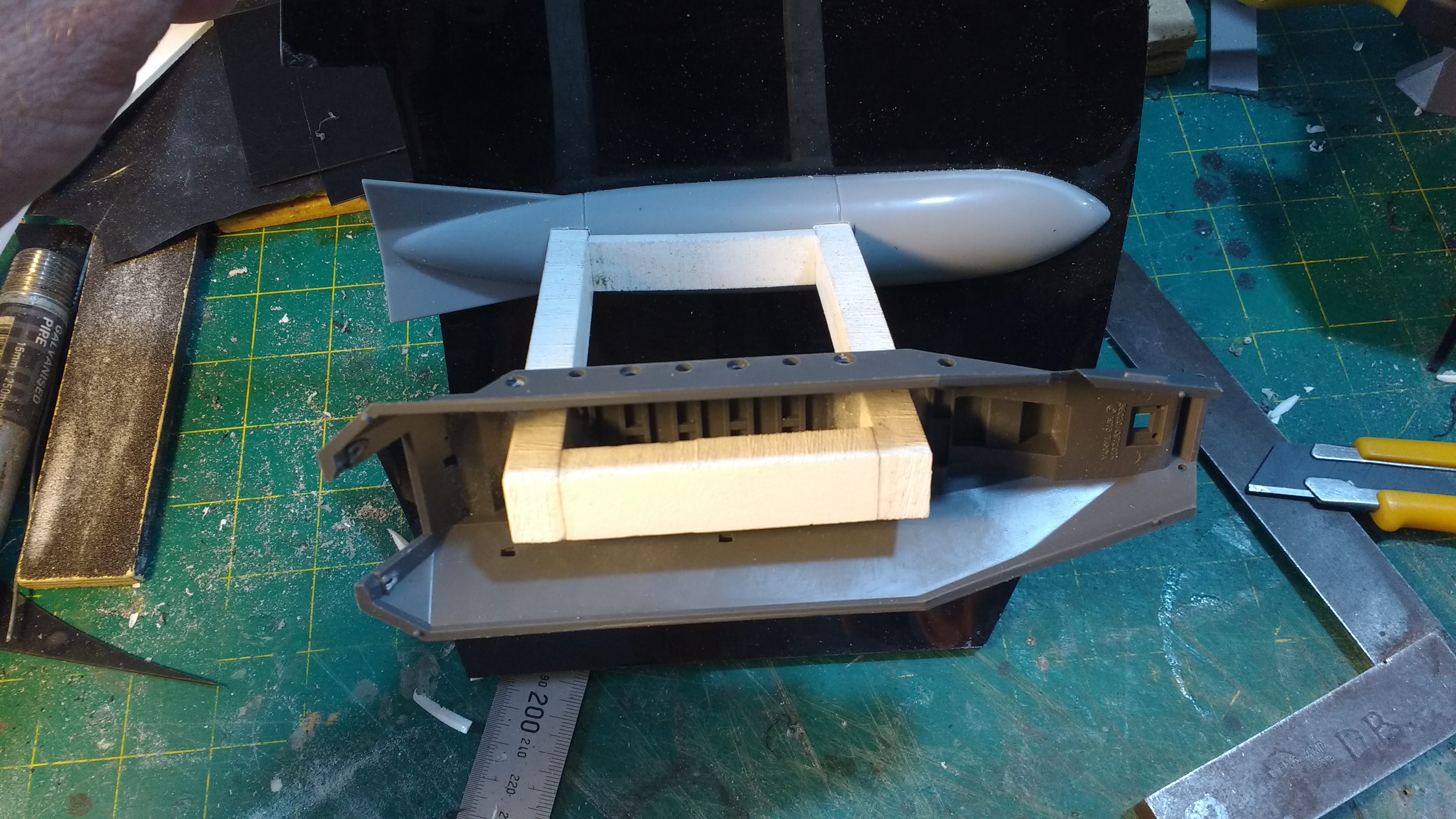
The tail was slightly shortened and the bottom section had a large slice removed from the middle so the front intake would be raked back at an angle. the tail fin was also sawn off and positioned further forward. I built a support block from 10mm PVC sheet with M12 tapped holes for mounting points on each side and the bottom. The threaded holes were doubled up with more 10mm sheet making them 20mm deep. power connections for the 12 volt supply use 2.5mm dc connectors. They are mounted to a small styrene plate so they can be recessed into the 2mm styrene sheet skin that will span the 75mm stretch gap between the two fuselage halves at the sides.


The interior intake was also glued together and then cut in half and filled in with 1mm styrene sheet. Small tabs were added so the sides could be aligned to the cut edges without falling in.
I'm using some 12 volt MR11 Led mini downlights for the engines again with the usual 2 pin ceramic connectors. The bulbs will have to be superglued in place as they are going to be covered in nozzles made from the propeller shrouds of the two Submarine kits I used in the Space Barge project.


The intention is to have the rear side panels removable for access to the connectors if ever needed.
A switch was added near the bottom power connector to separately switch the engine lighting on or off separately. The switch was mounted on a small piece of 2mm styrene and then a slot cut into the fuselage so it could be slightly recessed. I don't want the panel to ever push out of its slot when operating the switch so the panel edges were reinforced with baking soda and thin superglue.


Some LED lighting was added to the cockpit instrument panel. A small styrene box was made containing three LEDs, a red a white and a blue just for some colour variation with an opal perspex diffuser and attached to the back of the panel. A suitable resistor was added to the positive end so they will run at the 12 volts dc that will be supplied.
The cockpit interior was painted first before the lighting was installed


There is a 1/18 scale pilot supplied with the kit. He is unusually made from soft plastic and is assembled with metal pins making him almost a fully posable action figure except he is a bit floppy and cant stand and support his own weight. He will be fine seated in the cockpit however.


The next thing to tackle was the curved wings. I looked around for a suitable large radius to build on but all the buckets I had to hand were both tapered and too small so I made a simple jig from two curved bits of chipboard, pine spacers and skinned with a piece of 3mm foamed PVC. I attempted to skin it with some thin plywood I had lying around but it wouldn't bend easily and ended up splitting. The foamed PVC sheet curved easily and was stuck down with thick superglue with the assistance of a few squirts of zip kicker.
I did a couple of thumbnails to look at two versions of wing supports one with two supports to each wing, like an X and one with a single central support. I preferred the single support on the right similar to Fred Gambino's illustration so that informed the building of the wing structure.

First I made a cardboard template of the final wing shape and then when satisfied with the shape I cut a sheet of 1mm styrene and taped it down on the curved jig surface. I then added two 4mm solid square ABS strips and then struts of 2mm styrene cut into 4mm wide strips to build the frame. In the centre I added two layers of 2mm styrene to reinforce where the wing supports would be added with screws and superglue. The front curved edges were made from 4 layers of 1mm styrene pre cut into curved strips.
I will eventually skin the outer surface with more 1mm styrene and then detail both the inner and outer surfaces but that is yet to come.


Once the wings were removed from the jig they opened out a little to a slightly larger radius but that was expected . Wing supports were then constructed from 10mm foamed pvc. I am using the wing mounted fuel tanks from the Sabre kit at the junction of the wing and support with the other half of the tank going to be added to the outside of the wings. Where the wing supports meet the fuselage sides I am using the chassis form two Tamiya 1/35 Hanomag kits.
The wings were drilled for the screws and the Foamed PVC supports likewise with a smaller drill. The wing surface was prepared by roughing it up with coarse 80 grit sand paper and then thick super glue applied and the screws driven in making sure the support was aligned with the previously scribed lines.


Slots were cut in the tank halves so they could then be slid over the strut framing and cemented to the wings.


Similar slots were cut into the Hanomag chassis which was positioned with a Foamed PVC cross member and superglued after first roughing up the surface. 1mm styrene was used to skin the frame and small 16mm OD PVC conduit cut in half was glued to the ends. The front piece of conduit was drilled out to take a couple of kit part details, namely the engine cowlings from a 1/144 scale Kawanishi flying boat.


I also added the front side panels to the fuselage. The shape between the two hull halves at the front end is not a simple straight line so a template was required to get the panel outline. Wide masking tape was stretched across the void and then a pencil rubbed over the edge like a brass rubbing to delineate the cutting line. The tape was carefully transferred to some 2mm styrene for cutting out. That panel was then fettled a bit more by sanding and scraping until it fitted into the gap neatly.
Strips of styrene were glued along the inner edges of the kit hulls to receive the infill panel. The panel was carefully pre-bent by hand at the nose to better match the curvature and then the panel cemented into place with super glue being used over the area of the PVC mounting block. Before gluing into position a hole was made using a step drill for the the power connectors which were then glued in position and one made for the flanged nut on the mounting rod. The mounting rod can then be firmly locked into place against the PVC mounting structure. Circular covers will eventually be made to hide the unused mount holes.


I scribed panel lines on the new surfaces to match the kit fuselage and added a few small kit parts.


I have made one rear panel which is held in with a tab at the rear and two countersunk M3 screws into tapped holes in the PVC mounting block. These panels will have the wings attached so I have yet to see if any further screws might be required to hold it all firmly in position.


To be continued...


No comments:
Post a Comment