About this Blog

This is about the combination of two interests, Radio Control vehicles and Science Fiction models. This blog documents my science fiction spaceship and radio controlled vehicle projects.
Showing posts with label plastic model. Show all posts

Saturday, 28 March 2020

Moon Bus part 7

I had mentioned in Moon Bus part 5 that a suspension problem had stalled the project four years ago and that I had recently found a solution to cure the issue.

Back in the part 1 of this project I described making some adapters out of PVC to adapt the angled shock mounts on the Venom Creeper axles to support a vertical shock position and a sway bar link.
One of these broke with the model just sitting there doing nothing and I realised they were not up to the task. I needed to find a solution for the project to progress.

Four years later it dawned on me while waiting for a cycle to finish on the CNC lathe at work on how to make a better adapter fairly easily. The solution was to make it from some aluminium sheet and twist it in the middle to compensate for the angled axle shock mounts.

Original PVC adapters with the prototupe aluminium adapter below.


I made a prototype to see if I could make it work and it seemed like it would do the job so I made 4 good ones and fitted them to the axles.  I made them by hack-sawing and filing  some pieces of aluminium strip and placed each end in turn in a vice and twisted the middle to the required angle using a adjustable spanner. The two end holes were tapped M3  for the shock ends and sway bar linkage and the middle hole drilled out 3.1mm for clearance on the M3 through bolt and aluminium spacer which attaches them to the axle shock mounts.


With that obstacle out of the way the project continued and I did the work on the cockpit. Next up was paneling the hull.

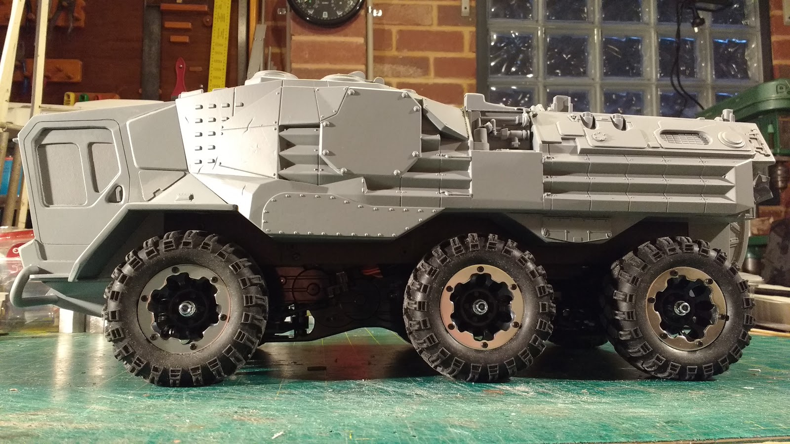
This was the hull as it has been sitting for 4 years.


I took that photo into photoshop and scribbled away very roughly to get some ideas for a panel layout. The picture below shows what ended up after a few rejected ideas and was enough to move on to a cardboard trial template which in turn lead to cutting some 1mm styrene.

Very rough scribbles in photoshop is all I needed to generate an idea for the paneling concept.

Cardboard trial template on left, 1mm styrene panel on the right.


I wanted to try for a sort of Data70 feel to the paneling. Data70 was a font designed in 1970 which when I was a kid represented the coolest sci-fi look ever.

Each panel was cut out using a step drill to cut the 12mm radius corners, an olfa knife cutting the straight lines with a metal ruler and a dremel sanding drum to complete. The panels had to be carefully pre-bent to match the curve of the hull. Some of the 1mm styrene was brittle due to sunlight and just broke up so frustratingly a few panels had to be made twice. The underlying skin on the hull was also made from the same batch of 1mm styrene and where it has seen some indirect sunlight it had started to craze and crack in a few places. I think the black styrene is more susceptible to this than the usual white styrene. The new panels have helped to reinforce the thin hull considerably and with the eventual addition of paint I don't foresee the cracking being an issue in the future.

There is more surface paneling to be done and a couple of solar panels to made for the top and a little more detailing still to go before I get to the primer stage.


The hull is increasing in weight as the panels and detailing are added. So far the shocks in which I added extra springs at the start of the project are holding up the weight just fine. I may need to make stiffer sway bars to correct any lean if it appears.

I would like to get the wheels anodised red to tie in with the rest of the colour accents on the chassis and maybe the chassis frames as well though that may prove to be outside my budget.

Thanks for looking.
More soon...

Part 1, Part 2, Part 3, Part 4, Part 5, Part 6, Part 7,

Sunday, 6 May 2018

Kong Head Toybash part 2

I believe I have completed the Kong Head Toybash build, I'll know for sure once the grey primer goes on.

I painted up the driver figures using some old Humbrol enamels after first spraying them with grey automotive primer. You can see that I also painted over the beard of one of them as well as painting on a different hairstyle. The flesh paint gave him a very pock marked facial skin texture. For the driver I added a steering yoke type set up out of a scratch made handle and some kit parts.


 I also made a console back lit by 6 amber LEDs which I forgot to get some photos of before securing the figures in the cockpit and masking off the windows ready for primer.


I decided to make the whole cockpit section removable rather than permanently cement it into position so that I can gain access should any need arise. It is held on by a lip at the top and a couple of screws in the bottom of the wheel arches which screw into a couple of wedges of foamed PVC and the styrene the toy body is made of.

 
The front of the cab was finished off with a bullbar bumper made from a plastic knitting needle heated and bent round a simple wooden former. It is secured in the middle by a brass tube and some holes in the 2mm styrene protrusions that make up a volume added under the cockpit that transitions back to the front suspension. The body is held on by two screws here that fix into a bulkhead on the Tamiya Kong Head chassis that normally holds the front bumper. The rear of the body is secured by a single long screw that goes through the Kong head rear Bumper into the 2mm styrene that makes up the rear door box.


Next up the model was cleaned with some wax and grease remover and sprayed with grey primer.


The grey primer tells me that the front cab section needs some more surface detail on the front and sides to match better with the rest of the hull, however the rest of the surfaces, I think, turned out reasonably well.


So I need to add a few more bits and pieces to the cab sides and then figure out a colour scheme.

More soon, thanks for looking.

Tuesday, 8 August 2017

ToyBash 2 part 1

True to form I started a new project, when I have so many others crying out for completion.

I have had the tracked lower section of the Bruder dozer toy from the original ToyBash truck project lying around without any concept of what to do with it . Very recently I acquired a Wall E Truck toy on ebay and when it arrived in the post I had an idea about combining the two.


But before that I wanted to be see if I could add a drive mechanism to the Bruder tracks so they could be radio controlled. I had a couple of gear motors, another ebay find, which were were very cheap at around $12.00 (including postage from China) and have  really well made metal gears inside a plastic housing. The question was would they fit into the space available in the Bruder chassis at the correct track width. After a bit of measurement it looked like they could be just squeezed in. I built a sturdy mount from aluminium angle and a bit of 3mm sheet and then hacked away at the ABS plastic of the chassis  so the whole unit could be slid into position. Some epoxy putty was slapped into the rear of the chassis and a piece of PVC sheet superglued in to the middle allowing for tapped holes so the mount could be securely bolted in place with m4 cap screws.


At 12 volts with no load they produce  only 70 rpm which may be a bit slow so we will see how that works out in due course.
The Bruder dozer has molded-in fake rollers that the tracks just slide over. I wanted to reduce the friction so I decided to try and modify the track supports and add actual rolling rollers. I hacked away all the bits of ABS that were the non-functioning rollers leaving the support brackets. These were then drilled to take a 2mm piano wire pin cut with a Dremel metal cut of disc. The rollers needed to be 16mm in diameter, I had some 12mm PVC rod and then found some PVC conduit in my stock with a 12mm ID and a 16mm OD, so in my mini lathe I machined up 16 sets of roller parts. I also made the top track return roller using the original molded ABS one I cut off. In the picture below you can see the modified track support above with the un-modified version still with the non-working rollers at the bottom.


I mostly used pair of electronic flush cutting nippers to hack away the unwanted plastic along with a razor saw and much careful sanding and filing. Below is another comparison of before and after on the track supports plus the new rollers and pins.


The separate roller parts were glued together with thin superglue wicked into the join and then once set they were assembled with the pins being retained with another small drop of thin superglue, being careful not to get any on the rollers. The result has been quite successful the tracks now roll smoothly along and the friction has been substantially reduced.


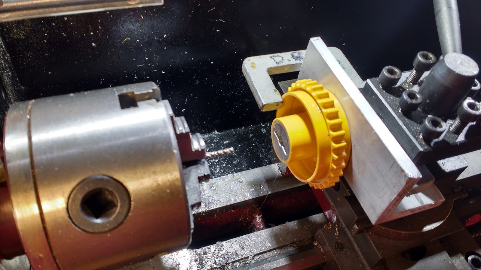
The next drive train job to tackle was the drive sprockets onto the motor gearbox shafts. Conveniently the output shaft on the motors has a M3 tapped hole in the end and a 3mm hole in the shaft to take a pin. I just had to machine a hub with a slot to engage with the pin. I had already made the hubs using some aluminium rod and glued them into the plastic sprocket wheel with thin super glue and baking soda to fill the gaps. It was after this I came up with the idea to mill some pin slots, so I needed a way to hold the sprocket in the tool post of the mini lathe spinning a 3mm endmill in the 3 jaw and use the cross slide to move the workpiece, like a poor mans milling machine.


 I cut a piece of thick aluminium angle and clamped it in the tool post. Then with a 2.5mm drill in the 3 jaw chuck, moved the carriage forward thus drilling a hole at the exact centre height of the chuck. This was then tapped M3 and the sprocket bolted in position through a pre drilled 3mm hole in the hub. The hub also has a 6mm hole that only goes about halfway in which is the size of the output shaft on the gear motor. With a tiny clamp stopping any rotation the slot was gingerly cut from the centre out in both directions a millimeter deep at a time for a total depth of 3mm.
This slot engages with a pin in the shaft locating it radially and axially at the correct track centre distance and the sprocket is retained with a 3mm cap screw into the the threaded portion at the end of the shaft.

Of course it would have been sensible to cut the slot before gluing the hub into the plastic sprocket but when you are working this stuff out as you go along sometimes the penny drops a bit later than would have been ideal.

I have yet to wire up the motors for a preliminary test but so far it all looks like it will work.

Now with all the major mechanical issues addressed what does the vehicle itself look like, well here it is so far...


I was originally thinking of using the Wall E cab but remembered I had a 1/25 scale truck cab lying around which I think looked a lot more interesting when combined with the digging tooth from the Bruder dozer. The cab section is held on with some screws so it can be removed and worked on separately.
Some acrylic plastic wine glasses from a charity shop are being used as tanks at the rear, covered with a plethora of pipes and kit part detailing. The whole rear tank module is removable (held on with a couple of cap screws into some more superglued PVC sheet drilled and tapped M3) so the motor mount can be extracted for servicing if necessary.


I thought the arms at the side of the Wall E truck which held some wacky tractor wheels could be re-purposed for some laser like devices making this some kind of laser mining vehicle. I had a Nerf gun toy that might fit the bill for this and found another one new for only $7.00 at Target for the other side. I removed the handle which is conveniently a separate part.


Various holes in the body have been filled with styrene strip and detailing of the surfaces has begun.


More soon...

Most Popular Posts in the Last 7 Days