About this Blog

This is about the combination of two interests, Radio Control vehicles and Science Fiction models. This blog documents my science fiction spaceship and radio controlled vehicle projects.
Showing posts with label Venom Creeper. Show all posts

Saturday, 19 February 2022

Creeper 6X6 part 8

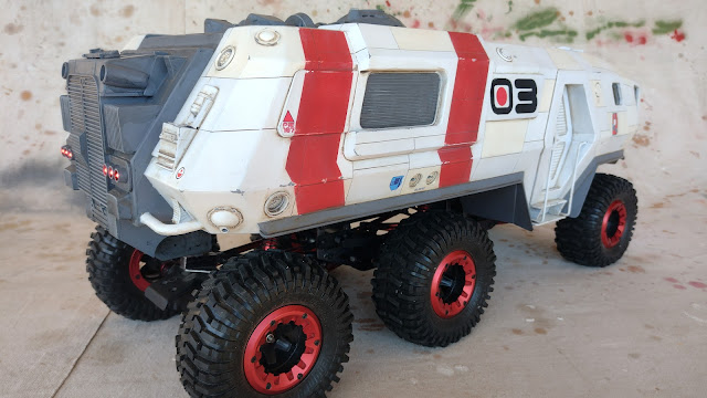
 The Creeper 6X6 project is now complete.

The primer grey model was sprayed with primer flat white and then random panels were masked up and sprayed with a satin off white colour and a satin white. All these paints are from spray cans of the Rustoleum 2X cover range. 


  I then took a photo at that stage and fiddled about in photoshop to determine a pleasing marking scheme.


The red markings were masked up and sprayed with an ancient tin of Humbrol flat red. The edges of the masking for the red markings had a few dabs of liquid latex masking medium to leave some chipped edges. Stupidly I only did this on one side forgetting to do it on the second side. Some dabs of white paint and some rubbing with a rag dampened with methylated spirits during the application of the wash soon remedied that omission. 

The numbers were designed on Inkscape and then printed out full size on paper. The paper numerals were then stuck with double sided tape to some masking tape applied to the model. The outline of the text was then carefully cut around with a scapel using a steel ruler for the straight bits and freehand for the curves. The number shapes were then peeled out and the numerals sprayed with flat black. It is not perfect up close but is good enough to pass.

That was left to dry out for a week and then I began the weathering process by applying a brown wash of Tamiya flat black and red brown mix heavily diluted with metho into all the scribed panel lines and around the edges of any detail. The grey roof detail sections received a flat black wash to further accent the recesses. Then using a metho soaked rag the surface wash was wiped clean in the direction of any desired streaks. The grey parts were then drybrushed using white students acrylic paint

The Humbrol red paint even after drying can still be loosened with the metho rag so I had to be careful not to rub it all away. I do however like the effect it has on weathering the paint, making it look sun and rain damaged. One just has to be judicious in the application and wipe off the red residue on the white areas which are not effected.

Using an acrylic grey paint I then added some chipping to the exposed bits of the body that would be susceptible to any graze damage. I also used applied this treatment to any paint finish anomalies to cover them up.  

The last thing was to add a few decals, mostly from the sheet I made up for the  Moon Bug project. Once the decals were dry I masked up the panels they were applied to and sprayed a coat of clear flat. The red dot in the middle of the black zero in front of the three is also a decal. It just happened to fit and I liked the graphic effect.

Finally here is the completed model.


Only eleven years in the making. I think it has turned out the way I had hoped when I started the project back in 2011. It was a very tortuous route but I learnt a lot along the way and it was the genesis for many of my completed RC vehicle projects.

Thanks for looking.

More soon...


Saturday, 5 February 2022

Creeper 6x6 part 7

 In the end I decided to scribe panel lines and not apply panels reasoning that this is a vehicle not a large spaceship and smooth surfaces are fine. I feel that in this case the scribed lines busy up the surface sufficiently and tie all the details together. Speaking of details I added a few recessed and flat round shapes here and there to represent access panels, water filling and dumping ports and recharging points.

Finally the model has reached the grey primer stage.


The plan for the colour scheme at this point is to be predominantly NASA white with grey detail sections and red markings very much like the science vessel project. The idea is that this is a well maintained and efficient vehicle not as beaten up and weathered as some of my past vehicle projects.

That will be heavily influenced by how well the painting process transpires. The more mistakes and painting mishaps I encounter will result in a more heavily weathered result to hide all those problems.

Sunday, 21 November 2021

Creeper 6x6 part 5

The last time I posted about this project was in 2017.  

With the Science Vessel project nearing completion I was thinking about which project to work on next. I thought it was high time this project was brought to completion.  

This RC vehicle project has been through a number of design revisions over its life with the current design being the third (and final) body with two previous designs having been started to be built and then rejected.

Link to the part 4 post.

In the last post I mentioned I was making a wooden buck to form a perspex window over for the front of the vehicle. That was done not long after the 2017 post and the project has sat around dormant since then.

Below you can see the wooden buck I made to heat bend the perspex windscreen. The buck and the perspex piece is made over size to be trimmed back to fit after bending. The trick to heat bending perspex neatly is to only heat the area to be bent. I use bits of thin sheet metal and you could use aluminium foil to mask the hot air from the heat gun off the bits I am keeping flat.


The first process was to apply the gentle curve to the front face of the window area. I heated the whole section masking off the sides until it was just slightly soft and used a cotton rag to press it down onto the former. Once cooled I used the sheet metal masking to just reveal a roughly 6mm wide strip for the corner bend. That exposed strip was heated and then bent using a flat piece of wood to push the perspex against the side of the former. This was then repeated for the other side. Once cooled it was trimmed to fit the front of the model and 2mm styrene pieces added. The picture below shows the result. The perspex protective film which was a plastic film was still on the undersurface. If the perspex had a paper protective layer I would have removed it first as it does not stretch like the plastic film does.


There is not much left to do to it other than wire up and install all the various light systems and complete all the surface paneling, and paint it  and the figures etc etc. Actually it seems there is still a fair bit to do and it always takes longer than I estimate.

In an attempt to lighten the very heavy body I hacked away at most of the interior bulkheads made from 6mm foamed PVC. This actually did result in a reasonable weight saving.

When I made the chassis originally I had provided a 6v power supply for any future lighting but as I now prefer to run all the lighting at 12 volts I replaced the 6 volt UBEC with a Matek booster board which has an adjustable output voltage. It takes  a feed from the 7.2 volt LIPO battery for the vehicles brushed motor and ESC and boosts it to an adjustable voltage in this case adjusted to 12 volts. In order to get a higher voltage than the source you must sacrifice some current but as I am only powering some LEDs which only use a small amount of current there is no problem.


 The 12 volts from the Booster Board then goes through a Pololu switch that plugs into the third channel of the receiver to remotely switch the lighting on and off via the push button on the transmitter.


In the photo above you can also see the sway bar arm on the middle axle. It is made from a length of solid brass on each side attached to the axle with a short linkage made from Traxxas rod ends. The bars at the other end are attached using a cap screw clamp to a length of piano wire with a flat ground on each end. A small aluminium spacer spaces the bar out from the chassis plates.


The control console is made from a 1/35 tank hull part with a perspex screen covered in a piece of black 0.5mm styrene with two video screen holes cut into it as well as a series of 1mm holes to look like buttons or indicator lights. Buried inside are 4 bright white leds in series, each dropping 3 volts making 12 volts in total. The occupants of the cabin are a couple of Bruder 1/16 scale figures.


 The photo below with a view down through the removable access hatch in the cabin roof shows the console in position.


All the lighting in the following photos are coming from the LEDS inside the console. The glowing edge is the raw edge of the perspex screen. I kinda like its effect so I may not paint over it.


I had an idea to make some sort of glowing revolving tech in a circular area on top of the roof that was yet to be detailed. I had  a bunch of cheap LED linear sequencing kits from another project and thought I might be able to adapt one to make leds sequence in a circle making a sort of rotating effect. The leds are white but there are some portholes painted with Tamiya clear blue which I added to the  the Pilgrim Explorer kit part I used which happily matches the diameter of the existing round shape on the roof.


The snag with this system is that it runs on 5 volts and not the 12volts I have for the rest of the lighting. I may have to re-employ that UBEC switched to 5v to power this device or use another board to drop the 12 volts down to 5 on the body. That may not be the most efficient way to do it, I'll have to experiment to see if that will work.

You can see the rotating effect in the short video below.


 I also made a communications array from some kit parts. The horizontal scanner is a part I was given some years ago. I think it is probably a Millennium Falcon engine part from one of those tiny Bandai kits. It also has the end of a disposable razor, a component I like to add to model somewhere, if at all possible.


The next task is to add some rear lights and then to complete paneling the surface.

Thanks for looking. 

More soon...


Most Popular Posts in the Last 7 Days