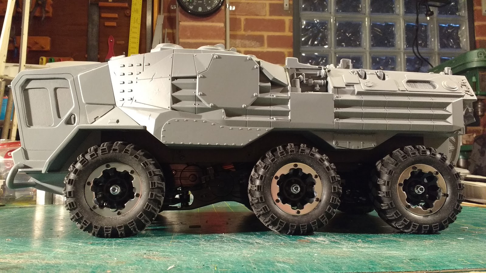
The name of this project series is due to the use of the use of Imex
Jumbo Maxx Swamp Dawg tyres which I like the proportion of a lot, sadly
no longer available. They are mounted to Monster Pirate wheels that have
a 17mm hex. These are then mounted to Traxxas 17mm hubs modified to fit
on the 6mm shaft of the Gear-motors, one for each wheel. Steering will
be spin steer, having a separate forward and reverse speed controller ( a Traxxas EVX2) for each side's three
wheels.
This is not exactly a new project, it has been hanging around in the background since the
motor per wheel test rig post way back in 2015. It had not progressed much since then as there were certain mechanical design issues that I couldn't see clear practical solutions to, until very recently.
One of the stumbling blocks was due to the length of the cheap gear-motors when attached to my simple rectangular profile aluminium swing arm design. That design, which I put to use in the
Reverse Trike project, uses a hose clamp arrangement to attach the motor to the end of an aluminium swing arm. Mounting the swing arm to the side of a chassis means that on compression of the suspension, the motor will foul the bottom of the chassis. One solution was to mount the swing arm out from the chassis so far that the motor no longer fouls. I wasn't happy with how this looked from an aesthetic and mechanical point of view. The alternative was to make cutouts in the chassis to allow the motors to swing into the vacant space. I couldn't see any simple way to do this until I happened across some parts for 3d printers on Banggood.com and then out of the blue a solution to the problem formed in my mind.
Essentially I found a simple way of mounting the swing arm pivots lower than the structural part of the chassis so when the arms swing up for full compression of the suspension the motors just clear the bottom of the chassis. I ordered the parts which were very inexpensive and waited for them to arrive in the post to see if it would work.
Here is the result so far.
The chassis is two lengths of 4mm thick aluminium angle which was actually a piece of aluminium channel which I cut down the middle. These are spaced apart with 10mm square aluminium rod tapped M4 and screwed together with button head cap screws. Onto these rails I bolted the parts from Banggood starting with 8mm rod mounts using the holes provided with m5 cap screws and nuts. The mounting holes for the cheap rod mounts were very inaccurately drilled, with a 1mm variation in hole centre spacing as well as being offset from the centre line You would hope that the manufacturers would be able to achieve better tolerances than shown on this sample of 6. I had to grind away a bit of the aluminium rails to fit some nuts on the inside as the holes ended up very close to the angle.
200mm lengths of 8mm rod ( it comes in that length and I didn't even need to cut it) is then mounted with a spacer of brass tube on the outside. These rods are the pivots for the swing arms and as a bonus considerably stiffen up the chassis structure.
The swing arms have two flanged bearings with an 8mm ID and 16mm OD fitted into the 16 mm holes drilled with a step drill in to the rectangular aluminium profiles. The swing arms are retained with 8mm collars that have a locking grub-screw. A small piece of shaped aluminium channel is pop riveted to the top of the arms to mount the shock which are Traxxas Summit or Revo shocks. The top of the shocks are mounted with 25mm M3 cap screws and an 8mm diameter aluminium spacer drilled and cut to length on the mini lathe.
I have been experimenting with the spring weights and wont know for sure what I'll use until the body is completed and the electronics and battery are all in place.
You can also see the hose clamp motor mount arrangement bolted to the end of the arm which has a circular cut out in its end the same diameter as the motor. This was cut very carefully with a hole saw in the drill press and then cleaned up with a file. The motors need to sit at 90 degrees to the arm or the they wont track straight.
Wires to the motors will be fed back into a hole in the swing arm (yet to be drilled) and come out the other end to be fed back into the chassis for connection to the speed controllers, one for each side as per the previously mentioned
motor per wheel test rig post. I might add that the swing arm motor assemblies were built shortly after the test in 2015 and have sat around in a box since then, waiting for that little spark of inspiration to progress. The position of the top shock mounting point was determined by moving it about to different positions and clamping it and testing for operation until a spot was found that gave the right amount of stiffness and compression. I did this originally with one swing arm mounted to a scrap of plywood, Once I mounted the swing arms to the chassis I moved the position around further until I was happy with the motion.
I am planning to build an under chassis cover that will hide all the mounting hardware leaving spaces for the motors to fold back into.
Next to be tackled was the design of the body. I've been toying with ideas for 6X6 vehicles for some years coming up with a number of designs over that time but never really finding one that exited me enough to start building. While running off 150 of the same part on the CNC machine at work recently, I doodled away on a bit of paper and came up with a thumbnail that I liked.
I then took a photograph of the chassis and the wheels with my phone camera, threw that into photoshop and tried to come up with a side view. My painting skills are pretty dodgy at best but I managed to come up with an image that I thought fitted the chassis and wheels in good proportion along the lines suggested by the thumbnail.
I then took that image into DraftSight and proceeded to draw up some lines and dimensions to start the build.
I then took this cad drawing and drew up onto paper full size the side view ready to cut some styrene, in this case 1.5mm thick. I chose the 1.5mm styrene over Foamed PVC in this case because for one I had a full sheet of it and the design is mostly flat sided or curved in only one dimension not curved in multiple dimensions like the Reverse trike project. It's not as heavy as 2mm styrene which I have used for a lot of previous projects and it's always a good idea to try to keep the weight down when making these vehicles wherever possible.
Here are some shots of the body structure under construction.
It starts of being rather flimsy at first but as the skin gets added the strength and rigidity increases.
Most of the edges get doublers to increase the gluing surface area and the bulkheads get small re-inforcing strips added to the inside of the skin for the same reason. There are only three bulkheads in the structure but I added some localised small buttresses in-between to help shore up the side panels and stop them flapping around while I beveled the edges to receive the bevel sheet which, as can be seen, is still to do. The cabin side wall is just temporarily stuck on with double sided tape to get an idea of its shape and proportion.
I dug out these small action figures ($3.00 from Target) which are 105mm tall making them 1/17 scale if they represent the average height of 1800mm. They could be a short 1/16 scale or a tall 1/18 scale as well. Anyway they seem about right for the size of the vehicle that I want to imply, generally pretty big.
Dont forget that if you click on a picture it will display much larger on your screen.
Thanks for reading, more soon...