
Anyway I have a lot of time on my hands but no income to purchase modeling supplies, the ol' catch 22.
I was cleaning up my shed and in doing so re-evaluated some of the old projects lying around unfinished. I had a bit of a brain wave about one of the unfinished spaceships which after some fiddling about with some shapes in the plastic junk box came to a dead end and then inspiration struck for the other unfinished and partly cannibalised project. This project initially started immediately after seeing Star Wars Episode one when it came out at the cinema, in 1999, 17 years ago. I was enamored with the Radiant VI or Republic Cruiser which closely followed the design precepts set in the original Star Wars trilogy. To my mind it was the best thing in Episode one and sadly gets destroyed a few minutes into the opening of the movie.
I am calling my variant the Resilient as it has bounced back from the scrap heap to live again.
As usual for me it is not a replica, it is my own version, a homage to the original.
For the beginnings of the story of this model, see this post from 3 years ago;
unfinished-old-spaceship-model-part-1
I pulled the main surfaces apart, stripped out the heavy steel spine and laid out the major parts on the ground with a pvc pipe spine, PVC pipe component engines, cardboard mockup engine mount shape and a toy rocket from a charity shop purchase.


The engine mount wing was cut from 10mm thick foamed PVC sheet, lightweight easy to cut and relatively strong. The 65mm (i.d.) PVC pipe spine was slotted to allow the engine section to slide into position and shaped to fit the engine pods. Each engine Pod is made from a 90 to 65mm PVC down pipe reducer, a short bit of 90mm storm water pipe and then a 90 to 75mm storm water reducer. You can see in the pictures above I had a short piece of 75mm storm water pipe in the ends of the engine, this I decided was unnecessary as they made the engines too long.
Inside the two outer pods a clear styrene dome was fitted inside the downpipe reducer. These domes were cheap Christmas bauble decorations which come in two halves which you can put things inside.
The outer engine pods were also partly slotted to make a strong fixing to the wing, glued with thick super glue. I may add some epoxy here as further structural reinforcement.


My engine arrangement is smaller in proportion to the one on the Radiant. Both the diameter of the engines is smaller and the spacing apart is less. This is due to the sizes of PVC components I had handy but I think it looks fine. When you look at the actual Radiant model from the top down (see the small picture in the Sculpting a galaxy book) the engines and their spacing is huge.
I made cones of 1mm styrene to fill the back of the engine pods and a couple of pvc pipe rings to hold the LED down lights for the engine lighting. The cones I had to make a few times as the black styrene I was using had absorbed some UV from a window nearby and got a bit brittle, it kept breaking. In fact one I positioned correctly and proceeded to glue into position with thin CA glue. A series of cracking sounds was heard and the whole cone fell into pieces, crazed and shattered by the thin super glue. I have found this to be the case before, thin super glue can crack thin styrene particularly if it is slightly aged. Thick super glue does not do this so I used that instead.


Ribs were fashioned from more 10mm foamed PVC sheet for the main hull section and slid along the spine and glued to the bottom 2mm styrene hull shell. Then the edge was built up from 2mm styrene. Strips of 2mm styrene are added to the tops as doublers so there is a bigger gluing surface for the top plate and the edges were sanded flush.
All the PVC to PVC glue joints are made using super glue and roughing up both surfaces with coarse sandpaper. This produces a very strong bond if done well and in my experience the PVC will break before the bond does. Foamed PVC glues extremely well with super glue as its edges present a slightly porous surface to the glue. The top surface I still rough up as although it has a fine texture it is a bit glossy. The PVC to Styrene joints are done the same way but are not quite as strong.


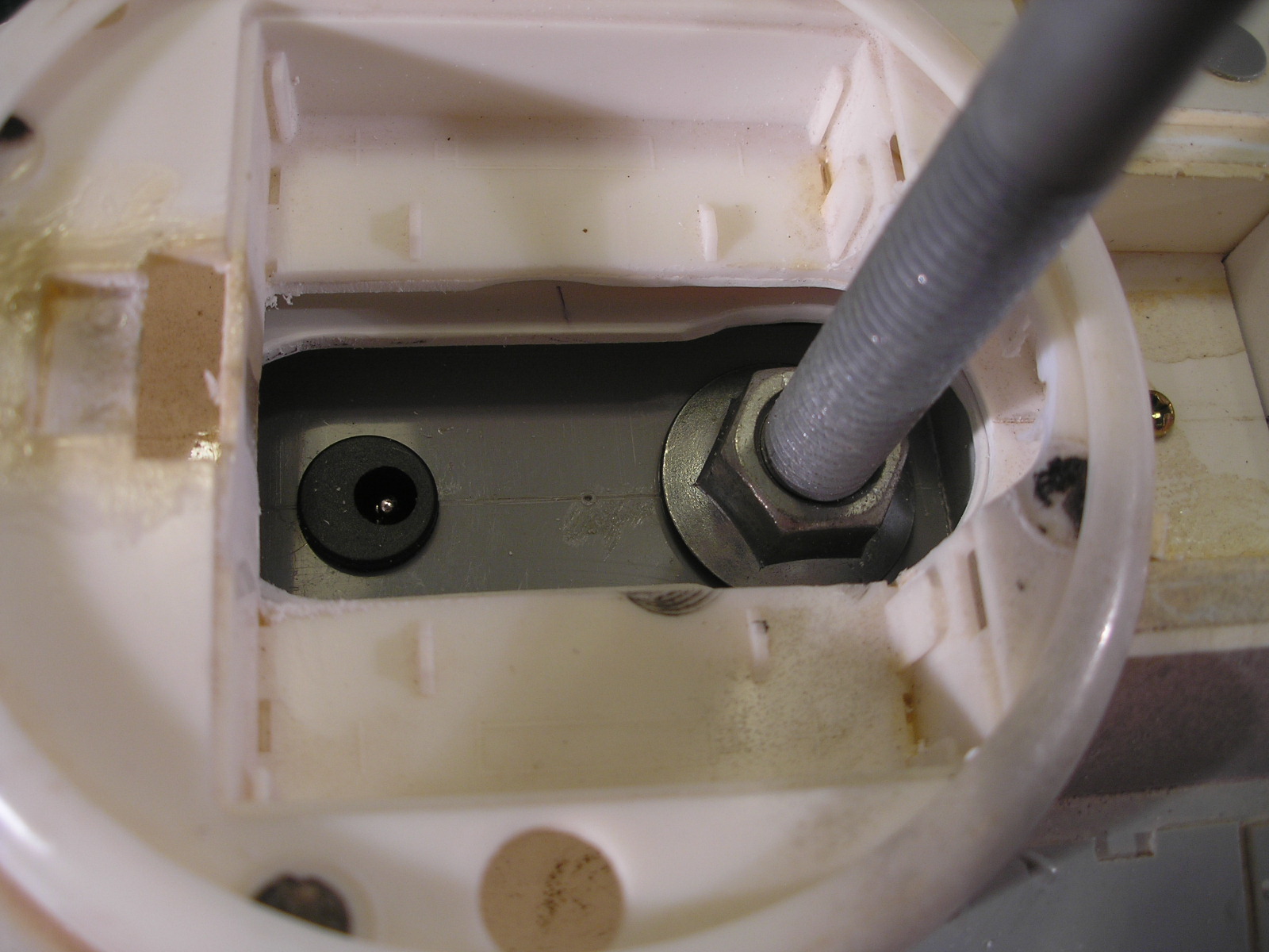
A mounting and power point block was made from laminated PVC sheet with two circles matching the i.d. of the PVC spine. The block constructed from 4 layers of 10mm PVC was drilled and tapped M12 for a M12 support bolt, the longest I could find at the hardware store at 280mm long. As this model is a bit longer at just over 1m, a bigger diameter support rod than I usually employ was called for. The cup head bolt was mounted in some round glued scraps of plywood onto a chipboard base as a work stand. later I intend to make a nicer looking display stand with another M12 bolt. A wiring harness was then made up to distribute the power to the engines and the cockpit and soldered to the dc power connectors (top and bottom) which were press fitted into a hole in the block, the wire leading out a adjoining hole in the back.


The mounting block was then slid into the PVC spine tube and glued with thin super glue through the engine mount slots and the support rod access holes in the spine.

The next step was to glue on the pre-existing top hull surface using Methylene Chloride solvent which I use for all styrene, ABS and acrylic joins to each other.


Putting it all together temporarily I found the engines were not sitting level so some remedial work was done on the slots to correct this problem and get them back into position. It does not seem to matter how much effort I put into keeping everything aligned errors always creep in and fixes are required. This is normal, it would take an elaborate jig to keep things square and I don't have the resources for that.
After some consideration I decided the toy rocket was too large and out of proportion to the rest of the ship and searched through the plastic shapes crate until I settled on the hammerhead arrangement that was on the model in the first place but with one of the acrylic cups swapped out for a cutdown acrylic wineglass. A 2mm styrene cockpit ridge was then constructed to fit. The top of the cockpit has been made removable for access to the power for the lighting and the fitting of a cockpit with occupants. I determined that 1/48th scale was about right so I need to source some pilot figures but that will have to wait until I have funds.


The window surrounds are made from black 1mm styrene. It took a few tries before I was happy with the sizing, you can see some of the rejects below. You can also see that The corners are drilled out with a 4mm drill and then the opening carefully cut out between the holes, a bit of filing or sanding to tidy up. These inserts are then cemented to the perspex window pieces which are already glued to the inner cockpit surfaces.

Here is the project so far with all the bits in place and major construction mostly done. The engine section is still removable at this stage for ease of working on it. It will eventually have to be fixed for the engine light wiring to be finalised.


More soon...
Part 2 is here


