The following is a an example of how a project of mine starts from a random idea to a possible physical reality. I do a lot of these preliminary processes on project ideas and there are many factors that determine whether the idea becomes an actual project and I start posting about them.
I find I have to really be surprised by how a project is coming together for me to push through to completion. It has to start looking as good or preferably better than what I imagined when I started for me to ignore the many distractions along the way. As soon as a project doesn't quite measure up to the image I held in my mind's eye at the very start, my devotion starts to slip away. If I then find I don't really like what I have done I lose interest and the project sits abandoned.
In the case with this body it still has something I like about it and I realised that I had not followed my own thumbnail closely enough. Somewhere along the way I had lost what it was I liked about it in the first place. The main problem was the front and those side windows which originallywent all the way down. After I made the front window I filled in the lower part because it didn't fit with the narrower aspect of the front window. This is due to the fact I never roughed out the front in a sketch. When I look at the thumbnail now I can see that I meant the front window to be as expansive as the side windows. In fact I imagined it going up over the roof stopping inline with the angled back of the side window. Narrowing the front window had ruined the proportions. I also constructed a much larger bevel along the top edge than suggested by the thumbnail. It no longer had the character that appealed to me to start with.
Sometimes with the passage of time a project can be re-evaluated and a spark of an idea to rescue it from abandonment surfaces.
I have been looking at possibilities over a long period for the rejected body for the creeper 6X6 project which is just lying around.
The picture below shows it on that Creeper 6x6 chassis and I just didn't like the way it sat, for me the proportions were all wrong, the wheels were too small and the chassis too long.
I have tried it on a few different four wheeled chassis with various sized wheels and it just never seems to look right.
The the other day I got the idea that maybe it would sit better on an alternative to tyres.
A quick photoshop session then ensued to rough out the concept and see if it had legs, or more specifically tracks.
Now to my eye that's much more like it, I think it sits well on those tracks which are from a M113 APC. I also changed the nose slightly to hint at a larger area of glass to the front which is a big improvement. It was time to move to an experimental phase as there was a big technical question to be answered.
Can I find some tracks that would do the job. I considered various Heng Long Tank chassis and tracks at 1/16 scale but they are too small to look right. Can I get a larger scale set of tracks? I found the very thing on Ebay, metal 1/8th scale tracks with drive sprockets to fit... but they cost way more than I can afford.
The next obvious question is can I make my own tracks that will be strong and work?
It was time to try an experiment. The first step was look at various tank track links and determine the simplest solution to engineer with my meager resources. Most of them are very complicated castings but I remembered the Tamiya Leopard metal tracks and how they easily go together from simple parts and decided to upscale that concept.
Next step was to rough something out in CAD which I did and decided it was too big so I drew up a smaller version you can see below.
The material I chose was grey PVC sheet. It is a material I am familiar with and more importantly I had some in 6mm which actually measured out to 5.6mm thick which is better for me. Sliced up some strips on the circular saw and chopped them off on a mini docking saw. Drilled holes and inserted brass brazing rod pins.
The pins are 2.4mm in diameter so the track pads were drilled 2.5mm for clearance. The cleats on the end of the pins which tie them together were drilled 2.2mm so the pins are a press fit and hopefully wont come off, a drop of thin superglue should do the trick if they look like loosening up.
The test showed that it would be possible to make them provided that the drilling was precisely spaced and square. To achieve this a jig would be required to make the job easily repeatable and accurate. It would be a tedious job as I estimate I would need around 124 links to make two tracks. There are 5 parts and two pins per link making 868 parts with 1240 holes needing to be drilled.
I was also thinking of adding a rubberpad to each of the track pads, superglue would do the trick here as it works very well on both rubber and PVC.
While I think it wouldn't be too difficult to make the idlers and the road wheels and even the suspension arms, there is the question of making the drive sprockets which would be another story in itself.
Will this idea proceed? There is a chance it will as I am enthused by the concept but I have a few other projects requiring attention at the moment so we will see.
Thanks for looking.
More soon...
About this Blog
This is about the combination of two interests, Radio Control vehicles and Science Fiction models. This blog documents my science fiction spaceship and radio controlled vehicle projects.
Showing posts with label tracked vehicle. Show all posts
Sunday, 19 January 2020
Tuesday, 8 August 2017
ToyBash 2 part 1
True to form I started a new project, when I have so many others crying out for completion.
I have had the tracked lower section of the Bruder dozer toy from the original ToyBash truck project lying around without any concept of what to do with it . Very recently I acquired a Wall E Truck toy on ebay and when it arrived in the post I had an idea about combining the two.
But before that I wanted to be see if I could add a drive mechanism to the Bruder tracks so they could be radio controlled. I had a couple of gear motors, another ebay find, which were were very cheap at around $12.00 (including postage from China) and have really well made metal gears inside a plastic housing. The question was would they fit into the space available in the Bruder chassis at the correct track width. After a bit of measurement it looked like they could be just squeezed in. I built a sturdy mount from aluminium angle and a bit of 3mm sheet and then hacked away at the ABS plastic of the chassis so the whole unit could be slid into position. Some epoxy putty was slapped into the rear of the chassis and a piece of PVC sheet superglued in to the middle allowing for tapped holes so the mount could be securely bolted in place with m4 cap screws.
At 12 volts with no load they produce only 70 rpm which may be a bit slow so we will see how that works out in due course.
The Bruder dozer has molded-in fake rollers that the tracks just slide over. I wanted to reduce the friction so I decided to try and modify the track supports and add actual rolling rollers. I hacked away all the bits of ABS that were the non-functioning rollers leaving the support brackets. These were then drilled to take a 2mm piano wire pin cut with a Dremel metal cut of disc. The rollers needed to be 16mm in diameter, I had some 12mm PVC rod and then found some PVC conduit in my stock with a 12mm ID and a 16mm OD, so in my mini lathe I machined up 16 sets of roller parts. I also made the top track return roller using the original molded ABS one I cut off. In the picture below you can see the modified track support above with the un-modified version still with the non-working rollers at the bottom.
I mostly used pair of electronic flush cutting nippers to hack away the unwanted plastic along with a razor saw and much careful sanding and filing. Below is another comparison of before and after on the track supports plus the new rollers and pins.
The separate roller parts were glued together with thin superglue wicked into the join and then once set they were assembled with the pins being retained with another small drop of thin superglue, being careful not to get any on the rollers. The result has been quite successful the tracks now roll smoothly along and the friction has been substantially reduced.
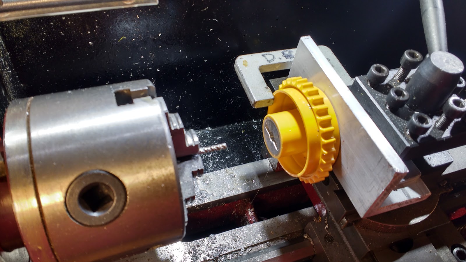
The next drive train job to tackle was the drive sprockets onto the motor gearbox shafts. Conveniently the output shaft on the motors has a M3 tapped hole in the end and a 3mm hole in the shaft to take a pin. I just had to machine a hub with a slot to engage with the pin. I had already made the hubs using some aluminium rod and glued them into the plastic sprocket wheel with thin super glue and baking soda to fill the gaps. It was after this I came up with the idea to mill some pin slots, so I needed a way to hold the sprocket in the tool post of the mini lathe spinning a 3mm endmill in the 3 jaw and use the cross slide to move the workpiece, like a poor mans milling machine.
I cut a piece of thick aluminium angle and clamped it in the tool post. Then with a 2.5mm drill in the 3 jaw chuck, moved the carriage forward thus drilling a hole at the exact centre height of the chuck. This was then tapped M3 and the sprocket bolted in position through a pre drilled 3mm hole in the hub. The hub also has a 6mm hole that only goes about halfway in which is the size of the output shaft on the gear motor. With a tiny clamp stopping any rotation the slot was gingerly cut from the centre out in both directions a millimeter deep at a time for a total depth of 3mm.
This slot engages with a pin in the shaft locating it radially and axially at the correct track centre distance and the sprocket is retained with a 3mm cap screw into the the threaded portion at the end of the shaft.
Of course it would have been sensible to cut the slot before gluing the hub into the plastic sprocket but when you are working this stuff out as you go along sometimes the penny drops a bit later than would have been ideal.
I have yet to wire up the motors for a preliminary test but so far it all looks like it will work.
Now with all the major mechanical issues addressed what does the vehicle itself look like, well here it is so far...
I was originally thinking of using the Wall E cab but remembered I had a 1/25 scale truck cab lying around which I think looked a lot more interesting when combined with the digging tooth from the Bruder dozer. The cab section is held on with some screws so it can be removed and worked on separately.
Some acrylic plastic wine glasses from a charity shop are being used as tanks at the rear, covered with a plethora of pipes and kit part detailing. The whole rear tank module is removable (held on with a couple of cap screws into some more superglued PVC sheet drilled and tapped M3) so the motor mount can be extracted for servicing if necessary.
I thought the arms at the side of the Wall E truck which held some wacky tractor wheels could be re-purposed for some laser like devices making this some kind of laser mining vehicle. I had a Nerf gun toy that might fit the bill for this and found another one new for only $7.00 at Target for the other side. I removed the handle which is conveniently a separate part.
Various holes in the body have been filled with styrene strip and detailing of the surfaces has begun.
More soon...
I have had the tracked lower section of the Bruder dozer toy from the original ToyBash truck project lying around without any concept of what to do with it . Very recently I acquired a Wall E Truck toy on ebay and when it arrived in the post I had an idea about combining the two.
But before that I wanted to be see if I could add a drive mechanism to the Bruder tracks so they could be radio controlled. I had a couple of gear motors, another ebay find, which were were very cheap at around $12.00 (including postage from China) and have really well made metal gears inside a plastic housing. The question was would they fit into the space available in the Bruder chassis at the correct track width. After a bit of measurement it looked like they could be just squeezed in. I built a sturdy mount from aluminium angle and a bit of 3mm sheet and then hacked away at the ABS plastic of the chassis so the whole unit could be slid into position. Some epoxy putty was slapped into the rear of the chassis and a piece of PVC sheet superglued in to the middle allowing for tapped holes so the mount could be securely bolted in place with m4 cap screws.
At 12 volts with no load they produce only 70 rpm which may be a bit slow so we will see how that works out in due course.
The Bruder dozer has molded-in fake rollers that the tracks just slide over. I wanted to reduce the friction so I decided to try and modify the track supports and add actual rolling rollers. I hacked away all the bits of ABS that were the non-functioning rollers leaving the support brackets. These were then drilled to take a 2mm piano wire pin cut with a Dremel metal cut of disc. The rollers needed to be 16mm in diameter, I had some 12mm PVC rod and then found some PVC conduit in my stock with a 12mm ID and a 16mm OD, so in my mini lathe I machined up 16 sets of roller parts. I also made the top track return roller using the original molded ABS one I cut off. In the picture below you can see the modified track support above with the un-modified version still with the non-working rollers at the bottom.
I mostly used pair of electronic flush cutting nippers to hack away the unwanted plastic along with a razor saw and much careful sanding and filing. Below is another comparison of before and after on the track supports plus the new rollers and pins.
The separate roller parts were glued together with thin superglue wicked into the join and then once set they were assembled with the pins being retained with another small drop of thin superglue, being careful not to get any on the rollers. The result has been quite successful the tracks now roll smoothly along and the friction has been substantially reduced.
I cut a piece of thick aluminium angle and clamped it in the tool post. Then with a 2.5mm drill in the 3 jaw chuck, moved the carriage forward thus drilling a hole at the exact centre height of the chuck. This was then tapped M3 and the sprocket bolted in position through a pre drilled 3mm hole in the hub. The hub also has a 6mm hole that only goes about halfway in which is the size of the output shaft on the gear motor. With a tiny clamp stopping any rotation the slot was gingerly cut from the centre out in both directions a millimeter deep at a time for a total depth of 3mm.
This slot engages with a pin in the shaft locating it radially and axially at the correct track centre distance and the sprocket is retained with a 3mm cap screw into the the threaded portion at the end of the shaft.
Of course it would have been sensible to cut the slot before gluing the hub into the plastic sprocket but when you are working this stuff out as you go along sometimes the penny drops a bit later than would have been ideal.
I have yet to wire up the motors for a preliminary test but so far it all looks like it will work.
Now with all the major mechanical issues addressed what does the vehicle itself look like, well here it is so far...
Some acrylic plastic wine glasses from a charity shop are being used as tanks at the rear, covered with a plethora of pipes and kit part detailing. The whole rear tank module is removable (held on with a couple of cap screws into some more superglued PVC sheet drilled and tapped M3) so the motor mount can be extracted for servicing if necessary.
I thought the arms at the side of the Wall E truck which held some wacky tractor wheels could be re-purposed for some laser like devices making this some kind of laser mining vehicle. I had a Nerf gun toy that might fit the bill for this and found another one new for only $7.00 at Target for the other side. I removed the handle which is conveniently a separate part.
Various holes in the body have been filled with styrene strip and detailing of the surfaces has begun.
More soon...
Subscribe to:
Posts (Atom)
Most Popular Posts in the Last 7 Days
-
This model was started around the same time as the "Sony" model. It is so close to being finished I don't know why I didn'...
-
The Ultraman production purchased a collection of miniature buildings that were originally made for an unfinished version of Total Recall ...
-
I've been continuing on with the trike project and have completed the construction of the exterior bodywork and added a rear mudguard, ...
-
This model was made in the late 90's. It was again made from a disparate collection of shapes. There is a central spine made of some PV...
-
I started a small kitbash project while waiting for some figures to turn up for the Industrial Structure project . Every year I display som...
-
I have at least 11, if not more, unfinished projects piling up in my shed. A few of them are so very close to being completed. The sensible ...