About this Blog

This is about the combination of two interests, Radio Control vehicles and Science Fiction models. This blog documents my science fiction spaceship and radio controlled vehicle projects.

Monday 28 December 2015

Escape Pod part 4

Primer is on.
It didn't take too long to dry as it was 36 degrees Celsius here in the south west of Western Australia today. The primer overspray dried as it fell. Went around with a scotch brite pad to knock of all the furry bits of primer.
I decided to chip a couple of the black 1mm styrene panels off the top at the rear as I didn't like them.
I forgot to replace the hole plugs when I took the photos.


  I will scribe some panel lines into the plainer surfaces.

more soon...

Escape Pod part 3

Most of the outer surface detailing has now been done. The black  bits are 1mm styrene sheet. There is still a few areas that may need a few bits added but I will spray a primer grey pass next to see where it's at before deciding.


I also finished up the retaining system for both hatches. The rear hatch has a plug that fills the hole for the support rod. The hole for the support rod also acts as the handle to pull the hatch up and forward to release. A couple of small round magnetic cabinet catches hold the hatch in place in each front corner. The steel washers from the catches are superglued to the under side of the hatch. You first have to roughen up the glued side with very coarse sandpaper so that the superglue can grip effectively, as well as allowing some to squeeze up through the counter sunk  screw hole. A squirt of accelerator helps the super glue to harden quickly.


The rear of the hatch is gripped by a long strip of plastic that hooks under the hull opening.


After stating on the RPF forum I wasn't going to hinge the canopy hatch, I went out and purchased a couple of tiny hinges and... hinged the hatch. The hinges are superglued to the hatch and to the hull again roughening up the glued surface, and in addition with a couple of m2 cap screws screwed in as part of the detail. The front is held in place just by the friction fit of the acrylic window into the hole in the hull. Some more positive closure may be required, we will see.


Next up is masking the windows, a grey primer pass and then starting the cockpit interior.
More soon...

Wednesday 23 December 2015

Escape Pod part 2

I did do a rough thumbnail sketch after I had figured out the arrangement of shapes, before construction just to set a direction to go in and later roughed out the cockpit window arrangement before I started the CAD layout.

I started the detailing the top and bottom of the engine section with various kit part nurnies.


In the thumbnail sketch you can also see a couple of canard winglets at the front and a rear wing which is what I decided to tackle next.
First, using scrap cardboard, I tried out the wing, cutting and bending until I was happy with the general proportions. I tried it backwards, forwards and in any possible position, finally deciding that the tips swept backwards looked best as it complimented the shape made by the angle of the handle of the dustbuster.


I then made up a wooden former to heat and bend some 2mm styrene to form the wing.
The styrene is marked out from the cardboard template and clamped to the former with some welding clamps. I always leave a generous allowance of extra plastic when heating and bending as the edges can slightly curl up or warp and then the desired shape can be trimmed to size.
 A sheet of metal ( in this case zinc, its what i had to hand) is used to shield the styrene that is to remain unbent from the hot air from the heat gun.  A piece of flat wood is used to shield the styrene past the bend and the heat gun played across the bend area untill the styrene starts to sag, The flat piece of wood is then used to roll and flatten the softened styrene to the former. I bent another piece of styrene over the first to get the next layer in the lamination that makes up the wing.


The two bent wing laminations were then glued together  with an extra strip of 2mm styrene between the two at the front giving the wing a thicker leading edge. I had to cut a dart into the top layer at the bends to get the rear to pull together at the thinner rear end. I then using more card board worked out the shape of the supports and laminated them out of three layers of 2mm styrene.


more soon...

Tuesday 22 December 2015

Escape Pod part 1

I have some holidays over the Christmas period so I started a small project which I hope to complete before returning to work in the second week of January 2016.

Some time ago I volunteered to make a CG spaceship and do a couple of shots for a friends sci fi short film. Although I designed and started to build a CG model, I changed jobs and moved across the country and so in the end was not able to contribute to the project.
Many years later, I again volunteered to resurrect the project and attempt to finish of what I had started. 5 years later finding that for me CG spaceships are  really not that motivating I thought about making a real model spaceship instead, an infinitely more appealing task...

The film requires an escape pod that leaves a dangerously disabled mothership. I have few old spaceship models that could be pressed into service as the mothership but I need to build an escape pod of some description. I had a rummage around in my plastic junk boxes and pulled out an old dustbuster which I have had lying around for years and a couple of desktop pen and pencil caddies I purchased a year or so ago.
I had started laying out the shapes, cutting the front of the dustbuster in half and spreading them apart
when my wife walked in and said " that is always going to look like what it is... a dustbuster"
I am not so easily dissuaded... to me the dustbuster always looked like part of a spaceship and never a houshold appliance.
I continued on.


This is the result so far using the previously mentioned plastic household items and some 1.5mm ABS sheet.


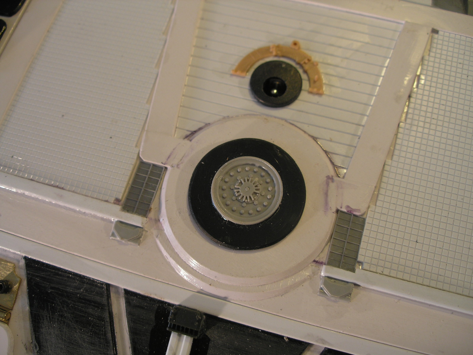
Again I am employing a 3/8 furniture leg plate as a mountng system and 12 volt led downlights for the thruster light effect. The lights locate into a circular hole in the back of the caddie thrust tunnels and are secured with a short length of aluminium angle with two rectangular holes cut into it which mate with the rectangular stubs of the lamps. Ceramic downlight connectors plug into the lamps.
All this is accessible through a hatch in the top of the model. A couple of magnetic cabinet catches at the front corners along with a styrene tab at the rear is proposed for the hatch retaining system.


Some cheap action figures from Target which scale out to 1/16th will populate the cockpit which is accessible through another hatch comprising the window section. Only one figure will be required for the short film so they will be made to be removable.


 The clear acrylic sheet for the window was heated with a heat gun until slightly soft and pressed onto a wooden form that matches the curvature of the hull shape using a cloth pad.
The window strut arrangement was drawn up in CAD using DraftSight and printed out full size with all the corner radius centres marked for drilling with a step drill to 10mm. The rest is then cut away with a sharp olfa knife and cleaned up with some minor sanding. A method for securing this hatch is yet to be determined.


More soon...

Moon Bus part 4

I have added some lighting to the model. I purchased a 1m led strip light that runs on 12 volts. You can cut the strip into any multiple of three of the surface mount leds and they will still work on 12 volts.
 The picture above shows what is left after cutting of all the bits I needed for the Moon Bus project.

You cut the strip on the line between the 4 copper contact pads where it says +12V. You then have to carefully cut away the clear covering over the contact pads and solder your wires to the pads. It comes with a strip of foam tape adhered to the back of the strip so it can be stuck into position.
They really throw out an impressive amount of light.
For the front I added a length of the strip to a piece of aluminium angle. A 2mm styrene box was then made to fit over this and secured with a styrene tab at one end and a dual ball cabinet catch at the other. A small 3 led strip has been added to the cockpit interior as an overhead light.


The rear lights were made from a two 3 led strips painted with Tamiya clear red. A similar styrene box, made to secure in the same way as the front, hides the wiring connection at the rear. Some kit part detailing has been added. A single white led has been added to the rear porch to light the rear hatch. A 1k resistor was calculated to be correct to run it from the 12volt lighting circuit.


To power the the lighting I will need a voltage booster to get 12 volts from the 7.2 volt motor battery.
The leds don't pull much current so I should be able to use a booster from Hobby King with no problems.

More soon...

Part 1, Part 2, Part 3, Part 4, Part 5, Part 6, Part 7

Most Popular Posts in the Last 7 Days