About this Blog

This is about the combination of two interests, Radio Control vehicles and Science Fiction models. This blog documents my science fiction spaceship and radio controlled vehicle projects.
Showing posts with label Sci Fi. Show all posts

Friday, 22 May 2015

Creeper 6X6 part 2 chassis

Creeper 6X6 part 1 is here

The original post for this from 2011 got accidentally deleted while I was trying to add a link to the next part, so I am going to recreate it here for a part 2.

Here is the Venom Creeper as it is supposed to be, a rock crawling RC vehicle supposedly to compete with the Axial  Rock crawlers. It was not as successful and has since been discontinued and for a little while back in 2011 they could be had new quite cheaply. I got a couple of the kits thinking I could attempt to make a 6X6 chassis. Others had already done this reasonably successfully so I had a go. One thing I particularly liked was the anodised aluminium beadlock rings which are very sci fi in design. The other aspect to the Creeper axles that i liked is they have a switchable diff lock, which means you can either have a working diff for tight cornering or a locked diff for better traction on rough terrain. As I have little regard to the "crawling performance" of these vehicles I thought they would suit my application just fine.

 I started by designing the chassis framework on a CAD program Deltacad.

This design was then printed out onto paper twice and spray glued to some 1.6mm thick lengths of aluminium angle. All the radiuses were then drilled out, after center popping them, using the radius centers marked on the printout. Then using a scroll saw and a lot of blades really designed for wood I cut out the rest of the material that made up the holes in the truss structure. Much careful filing later I had a pair of frames that the rest of the venom assemblies could bolt to.


 What you see here in these pictures is circa 2011. I eventually swapped out the shocks and their mounting positions many times over until I had a suspension system that could hold the weight of the top heavy body without flopping to the side. The added on rear axle is connected to a creeper frame cut in half, with many spacers made from 6mm aluminium rod on my Unimat 3 lathe.


It was quite a fiddle to get it all to work without binding or fouling, especially the front wheels which are turned for steering.


More recently with the new stiffer shock setup there is not the same amount of articulation as shown in the previous photos.

I then turned my attention to the body design and did a number of rough thumbnail sketches. After choosing the one i liked ( at the time, but ultimately abandoned and replaced) I roughly modeled it in Maya to get a sense of the volumes and proportions.


I then built a wood and plywood frame as a basis to start hacking into some 2mm styrene.
However I didn't really like what I had done and it sat around till this year 2015 when I did another thumbnail sketch that got me enthused and cutting plastic.


more soon...

Saturday, 8 June 2013

Old Spaceship model Part 2

This is  the oldest model I still have. It was made in 1985 or 1986. I was working as an industrial model maker as briefly described in my previous post, and was much more confident in trying out some new techniques. It is heavily inspired by some concept work that Chris Foss did for an unfilmed version of Dune seen in the book 21st century Foss. It was mainly the striated colours that I appropriated for my own shaped spacecraft but most people recognise the Fossian influence. In fact it was this model along with another spaceship I no longer have, that I took in a suitcase with me across the country to Sydney, at the end of 1986, in  an attempt to get work in special effects. The attempt I might add was successful.


The model was shaped out of a block of green polyurethane foam and then skinned with glass cloth and polyester resin. After lots and lots of sanding and primer and spray putty and more sanding, more primer more spray putty, more sanding... you get the idea..I ended up with a reasonably smooth shape. Model kit parts were sparingly applied. Recessed sections were superglued into holes cut into the skin. The engine nozzles were some smaller scale pvc pile guides as described in the previous post, with added strips.

You can see some damage from having been dropped.  To be expected after all these years and having had small children when the model was displayed on a shelf.

The interior nozzles were parts from a Micronaut toy from the late seventies.

The attitude thrusters were the wheels from a micronaut toy.


The patterning was done by spraying the model red and then freehand painting liquid mask on the bits I wanted to stay red, then spraying blue.
Very faintly seen in the photographs are panel colouring variations. It took forever to apply hundreds of tiny masking tape rectangles which were then over sprayed by a light dusting of white to produce the lighter shaded panels. It should have been a heavier application as it is barely visible. A few random small decals were applied along with lots of the kerning marks from rub on letraset sheets to represent windows.
The model is 650 millimetres long.

Old Spaceship model Part 1

I thought it might be interesting to look at some of my old Spaceship models starting with this one. While this model is not strictly an RC vehicle, it is most definitely SCI-FI and it proves that I do sometimes actually complete a model. This was made in the early 90's so its about 20 years old and  the length is 880 millimetres.
I have never been interested in building replicas of famous craft, I always wanted to build my own designs, and I particularly find enjoyable the process of arranging found objects into something new. You get arrangements of shapes that you would never have come up with if you just sat down with a pencil and paper and tried to design it from your imagination.


The front ball shape command module was from a baby's toy that rolled along the ground with small coloured balls inside. The window section is an upside down front of a 1/25 American car kit.


The neck was made from some PVC pipe which had been heated at one end and stretched into a cone shape. These PVC shapes were sourced from the industrial model making company I used to work for early on in my working life. They were reject pile guides made for a 1/33 scale North West Shelf gas platform model. In Western Australia there were a lot of these "plant and piping" models being made for the many resource projects in this resource rich part of Australia. When I started there in 1985 I was working on the plant and piping models for the Argyle diamond mine project. The models were built as part of the engineering design process and featured all the complex pipe runs through all the plant areas. The models were used as a double checking process, to check that all the engineering drawings were accurate and to see if there were any obstruction  and clearance issues. The piping drawings were all isometric, just bent lines with dimensions. Sometimes errors would crop up, A pipe going through the middle of a steel girder or machine etc. The engineers would visit and have little 1/33 scale men on rods to poke about in the models to check head clearances and so on. All the piping and vessel parts would be from EMA, they used to have a massive stock of the stuff. Of course all this is done with a computer these days... ho hum.


 The little dome shapes are plastic fishing float cut in half, glued to small plastic jelly molds. The main rear hexagon was a plastic terrarium with a plastic bowl glued to each end. Note the plastic coffee stirrer detail, the paddle shape with three square holes. Can you still get these?


The engine bell is an acrylic cup. Inside the bell (not shown)  is an acrylic plastic tap handle.

Underside. There is a famous railway girder bridge kit part lurking there, a Thunderbirds model detail classic.

The round vent shape is the vent from a Millennium Falcon model kit. Nothing is sacred in the quest for detail parts.
 The paint finish is just the usual primer grey with some orange accents. It is heavily weathered with an application of my special "Poo Juice" mix which consists of roughly one part Tamiya Flat black to 5 parts Methylated spirits. This is liberally applied to all the nooks and crannies and left to dry. It is then wiped off with a metho soaked rag leaving it only in the panel lines and crevices. This will only work if the underlying paint does not dissolve in alcohol, so acrylic car primer and turps based Humbrol enamels are fine but other water based hobby paints which are alcohol based (like Tamiya) are no good. In fact even the enamels and the acrylic car paints need to have been dry for at least a couple of days before wiping over with alcohol ( metho). After this has dried completely I then dry brush white students artists acrylic paint over the raised areas. The student acrylic is very thin and transparent, so it just ends up lightening the raised areas in a pleasing manner. I use a palette of wood for the dry brushing which helps to suck up some of the moisture in the paint, making the dry part of dry brushing a bit easier and I use a very stiff oil paint brush. This is probably pretty crude for those used to subtle pastel shading on military models but in my experience of models for film and TV, you need to really exaggerate the weathering for it to show at all. The old rule of thumb when estimating what would ultimately be visible on the screen for model making was to squint your eyes, if it isn't visible when doing that, it wouldn't be visible on the screen.


Friday, 18 January 2013

Explorer Part 2

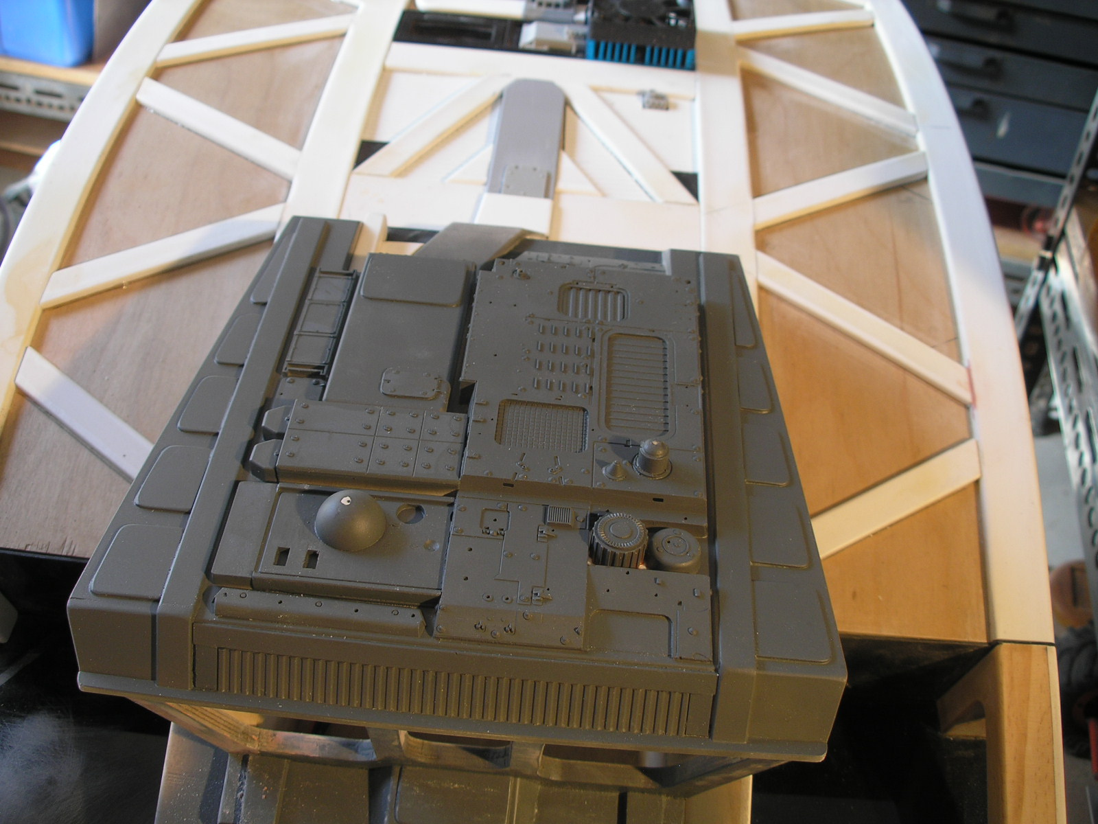
I have now done some of the detailing work on the back and built and detailed the roof of the cab.
It doesn't look like much until you hit it with a can of grey car primer. I intended to show the cab roof before and after the primer coat, but unfortunately got carried away and sprayed it before taking the photos. I always get excited when detailing, its the bit I enjoy the most. The tan coloured parts are from a 1/72 matchbox German tank kit, the dark grey from the ubiquitous 1/72 Hasegawa Leopold kit and the rest from a new purchase, a Trumpeter 1/35 Stryker kit., plus a bit of Evergreen, sheet styrene, bits of PVC and more pieces of 27mhz radio Control unit.


The photo below shows the stsrt of the upper hull detailing. The black ribbed panels are the sides from an old 27mhz radio control unit. You can also see an old computer CPU fan which will become some sort of airconditioning unit. It still works and I may hook it up to a power source. I need to come up with a grill to cover the fan.

 Here is the rear section with one grill installed. This was made from a sandwich of styrene strips glued up as one block then cut up to fit on the bandsaw.


 Here is the roof of the cab, detailed with the main top hull of the Stryker cut up and rearranged along with other parts and styrene ducting etc.


More to follow soon.

Part 1, Part 2, Part 3, Part 4, Part 5, Part 6.

Monday, 14 January 2013

Explorer

I'm ashamed to say it's been over a year since my last post. My modelling is usually in binges, in other words I do nothing else for a while until I hit a technical or design snag or lack of funds, then leave it alone. In the intervening time I have been learning about and building a couple of valve guitar amps and I'm halfway into a wooden sailboat build. Eventually I get my modelling mojo back and dive back in.

So I now present... a totally new project, the Explorer. It's some sort of mobile planetary exploration vehicle, a travelling laboratory and living quarters. It is based on Traxxas Summit running gear mounted on an extended Revo 3.3 chassis. The inspiration has come from "Snow Cruiser" an Antarctic explorer built in 1939.

Snow Cruiser 1939
Snow Cruiser was a roving base for a crew of 5, consisting of four 10 foot high electrically powered and individually steerable wheels. It housed two 150 hp diesel generators to power the electric wheel motors, as well as living quarters, kitchen,machine shop, photo lab, communications and storage for a years supply of food.

Yes, I know I haven't finished any of the other projects yet, don't worry I will get back to them, eventually.
All the parts were sourced from the usual place Ebay, from the many RC parts-stripping vendors who buy new kits, and break the model down into components to sell off cheaper than the pre-packaged spare parts.


I've got an older EVX2 speed control which doesn't have low voltage cutoff so I have added a Novak 2C Smart stop unit. The Summit uses two battery packs which connect in series internal to the ESC. The smart stop is wired in with one of the ESC's battery connectors, the side which provides the BEC. It means that only one of the packs is being monitored by the Smart stop, but you can assume the other pack is discharging a similar rate. Here is an extremely helpful wiring diagram courtesy of SuicideNeil from robotwars.00server.com.
Extremely helpful wiring diagram courtesy of SuicideNeil from robotwars.00server.com
Note that the two Titan 550's are replaced with a single Titan 750 in this application. The E Revo uses a pair of standard motors whereas the Summit uses the one larger donk. The new version of the Smart Stop is self sensing so it can cope with 2c-4c packs. There is a pile of much cheaper alternatives from Hobby King which plug directly into the balance lead of the pack which is pretty simple and convenient.
This larger motor is the same size as used in many cordless drills, I have one out of an old Panasonic drill which even has a 32 pitch pinion gear mounted which mates happily with the Summit transmission.


Two aluminium angle battery trays have been attached with my usual aluminium brazing rods.
There is still some work to do on the chassis, bracing the battery trays and a micro servo mount for Hi-Lo gear changing duties. One of the other features of the Summit is remote diff locking, at this stage I think I will just leave that as a manual switch rather than getting the push rod runs sorted out for servos.
I will also need the stiffest springs I can find, the purple ones, as the body is likely to be relatively heavy. Most Rc vehicles are designed to haul around a lightweight Lexan body however in the world of RC-SCIFI it is more likely going to have to deal with a heavy hand made shell loaded with "stuff". The suspension is one of the main technical obstacles to overcome, coping with the extra weight. It has consequences for the drive line as well, but most RC vehicles are engineered for extreme speed and that comes with a degree of over engineering that will cope with greater mass at the lower speeds that these SCIFI models will run. It just means gearing down for torque, rather than up for speed.
The two speed of the Summit tranny is perfect for this.

The tyres and wheels are Proline, They are huge, 3.8" 40 series, 175mm tall, 87mm wide on 17mm Traxxas hubs.

With the chassis well on the way, I turned my attention to designing a body. I started a few rough thumbnails, when I say rough I mean really rough.
Armed with these I drew up a full size side view template on cardboard, checking against the chassis.
I used 6mm ply wood ( probably overkill but it's what I had lying around, my philosophy is use up what you have, first) for the structure. I bored and hole sawed out lightening holes wherever possible.
It was all glued up with Aliphatic wood glue which is immensely strong but slow to dry. Other less critical wooden components used a fast set pva glue. The top of the shell was skinned with 2mm plywood, again because I had a piece the right size and because the wood to wood bond is very strong.


Sections are skinned with 1mm high impact styrene sheet, which in this case happens to be black. It is more usually white, but its what my local supplier had. It is much cheaper to source this styrene sheet from a plastics supplier than buy the tiny expensive sheets in the hobby store. This model is BIG it uses a lot more materials than a 1/35 scale military diorama. The styrene is sanded to provide a rough "keyed" surface for the green Zap-a-gap superglue to bond well with the wood parts. Some judicious applications of zip kicker accelerator also help with bonding to wood. The super glue joint is very brittle and is generally not good for parts subject to shock. An RC vehicle is often subject to shock, hitting things due to mistakes or poor driving, however when there is no better method of attachment it is used. As there is a very strong and resilient wooden under structure it should work out fine here.

Styrene to Styrene bonding as well as acrylic ( perspex), I use Methylene Chloride, a known carcinogen. Unfortunately there really isn't anything better. I make sure to use it with excellent ventilation, I usually have a fan moving air past the work area and doors and windows of my shed open for fresh air flow. It is applied with a cheap nylon modelling brush from an EMA pump dispenser which I have had for years ( a very long time ago, before the advent of Computer Graphics, I was a professional model maker). The plastic container perished so I replaced it with an old poly- ethylene ink container. Poly-ethylene is not dissolved by the Methylene Chloride.
One brush has a bent end which enables getting the solvent to spots difficult to reach, undersides and the like.


Finally here is a view of the body work so far.

I realised once I started that the original design did not allow any room for the cockpit because of the huge wheel wells. So a re-design was in order, raising the cockpit up higher and changing the scale a bit. I did another rough thumbnail to sort that out. As it turned out this is closer to the original Snow Cruiser concept.


Redesigned cockpit


I decided that it was about 1/12 scale so had a look in the local toy store for suitable figures and found these 1/12 Star trek figures going cheap which would suit perfectly.


 The idea with the body was that it was some sort of welded truss construction, with infilled panels.


The white strips are cut from 47 X47mm 4mm thick pvc angle, used for Hardy panel (fibro cement) building corners. Again the gluing surface is roughed up with course sandpaper for the super glue to key. Pvc sticks quite well with super glue as long as it is sanded first. The PVC here is actually a type of very dense foam, so it is not quite as heavy as solid PVC sheet, being about half the weight. The foamed PVC in sheet form, is, or was, a common material used for movie miniatures. It is not effected by methylene Chloride, so it has to be bonded with PVC cement or superglue. Styrene parts have to be superglued to it.

Rear detail is from an old 27mhz am radio control unit.
Test layout of some detail parts, sides from the RC control unit and a part from a Leopold model kit, plus a cpu fan which will become some sort of air conditioning unit.

Domes cut from PVC pipe end caps.
Inset detail from disposable camera parts...

...which get hidden behind a grill, made from the battery door of the radio control unit.

These are the door panels, made from an old modem. More detail to be added.

As predicted, this body is indeed quite heavy for the suspension. The current front springs are drooping to the floor at the moment, notice the block under the front holding it up. I hope the purple springs will cope. I may have to custom make some stiffer ones or get them made, we will see.

 That's it for the moment. The next post will not be a year away, it will be soon, I promise.

Part 1, Part 2, Part 3, Part 4, Part 5, Part 6


Most Popular Posts in the Last 7 Days