About this Blog

This is about the combination of two interests, Radio Control vehicles and Science Fiction models. This blog documents my science fiction spaceship and radio controlled vehicle projects.
Showing posts with label Creeper. Show all posts

Thursday, 13 July 2017

Creeper 6x6 part4

Guess what?... I decided, in the end,  that the body I was making for this project didn't really look right on this chassis, it was too tall and proportionally too short. I also found that I had not captured the essence of the thumbnail in styrene, particularly with respect to the  cabin area which suggests an expansive area of glass. The one I ended up making has a small constricted windscreen which was not  what I had originally intended.
I have stored that version away for some future project and for a front end re-build and substututed a new design, making it the third and definitely final attempt at a body that suits this chassis. In fact it is similar in proportion to the first version but in my mind much better realised.

Here is the version 2 thumbnail for reference;


 And here is the version 3 thumbnail;

I further reduced the height of the body when doing a rough CG model.


I then cut up the CG model into thin strips at the points I wanted to make bulkheads and deleted the rest of the geometry. A screen captured front view is then used as a tracing guide for a 2d Cad drawing that is then printed out and stuck on 6mm foamed PVC sheet and cut out making frames and bulkheads for the real model.


Here are some pics of the frame construction which is then skinned in styrene sheet.


You can see I have attempted to make the frame as lightweight as possible, it will still turn out pretty heavy once all the styrene skinning and the detail parts go on. It is however a pretty strong structure.

Here is the old version 2 body on the chassis, showing to me at least, it just does not seem to fit followed by the new improved version 3 body on the chassis.


And here's the detailing so far;


Look carefully below and you may spot some keys from an old computer keyboard and some heat bent bits of green plastic knitting needles.


 I have also partly done the cockpit and re-assigned the 1/16 scale Bruder figures from the Moon Bus project. The seat padding is made from bits of 3mm Foamed PVC sheet and the headrests from 6mm. There is also a magnetic cupboard catch in there above the crew door holding a roof access panel down.


 I am in the process of making a wooden form to heat shape some perspex sheet to make the large area of curved front and side windows that will go in the gaping hole that's there at the moment.
I have also got a back end of a 1/35 scale tank kit which will become a centre control console which will house some LED lighting.

Hopefully more soon...

Sunday, 7 June 2015

Toy Bash Truck part 3

Part1, Part 2, Part 4, Part 5


I made up pairs of headlights using some Cree Led aluminium penlight torches I got from China on Ebay. The torches worked out costing about $4 each which I thought was a pretty good deal. They claim they put out about 1000 lumens, I suspect it may be a bit lower than this but they are incredibly bright for their size and only use 1 AA battery at 1.5 volts. They conveniently unscrew at the business end making for a really nice lens and reflector housing, and are easy to mount and solder some wires to.


I wired them up 4 in series thus requiring a 6 volt supply. The battery for the chassis is 7.4 volts so I am employing a Turnigy Ubec which can deliver a switchable 5 or 6 volts at 3amps from any input battery between 2s or 6s which in LiPo battery speak means between 7.4 and 22.2 volts. These 4 penlights are only pulling 1 amp from the battery so there is plenty in reserve.


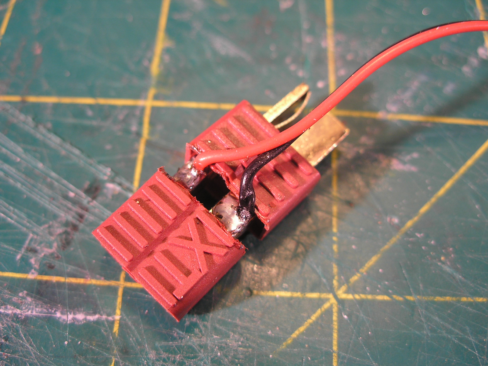
The Ubec is wired to a little adapter which is made from a deans connector plug and socket soldered back to back with the feed wires coming off the positive and negative at the join. The join is then covered with some suitable heatshrink. It is a convenient way of plugging it in between the battery and the speed controller. The lights are wired to a servo extension lead with one end cut off and the appropriate end plugs into the servo style female connector on the output of the UBEC which stands for ( Universal Battery Eliminator Circuit). In the old days of RC you used to have an extra separate battery for the receiver, servos and any other electrical systems it is this legacy battery that is supposedly being eliminated by the UBEC.


The lights are switched by a push button toggle switch mounted on the side of the cab which when painted will just look like a  random bit of detail. It probably would be cooler to make a switch that can be controlled from the transmitter, I am only using 2 of the three channels, but that was laying around in a box so I used it. I like to use whatever is to hand where possible.


The cockpit has been started but still has more work to come. A 1/16 Bruder Toys man sits in the seat. I'm thinking of making some sort of space helmet and converting his rolled up sleeves to be more space suit like.

I made up some tanks from PVC pipe end caps and the next size up pipe which has had a slice removed from its circumference to bring it closer to the outside diameter of the caps. Mounting pieces were made from 10mm foamed PVC, first a hole is made of the same diameter of the pipe and then sections are cut to suit. these slightly domed end caps are getting hard to find. All the new stock at the hardware store have totally flat ends which are not as interesting a shape and I can make those myself easily enough with a disc of flat sheet.


The chassis was shortened at the front to fit the body work that has been built, but yet to be detailed. The olive green radiator looking shape is a leftover spare part from a Tamiya Wild Willy Jeep kit.


More soon...

Saturday, 30 May 2015

Toy Bash Truck part 2

Part1, Part 3, Part 4, Part 5


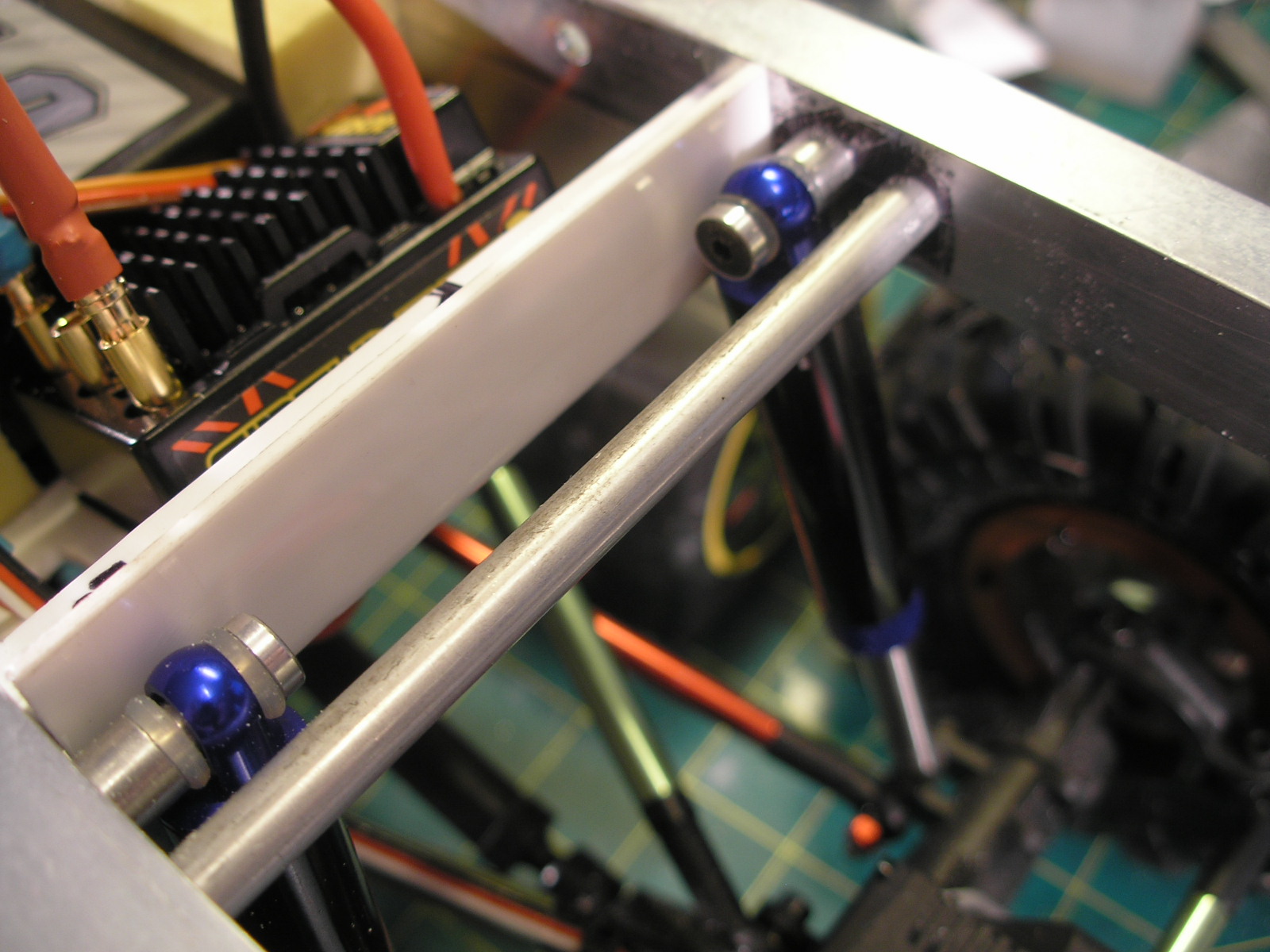
I finally completed constructing the chassis.The creeper chassis plates have been extended by some aluminium angle and channel section. The plates are held apart by some 6mm and 8mm aluminium rod spacers that have been drilled on the mini lathe and threaded at both ends to accept M3 cap screws.


The shocks have been mounted to the link mounting points on the axles with the links moved inboard. A piece of silicon fuel tubing has been inserted as a flexible bush into the hole in the shock shaft to allow some angular movement.


The top of the shocks use the mounting system that is included with the Hot racing shocks. These include a couple of silicon O rings and an aluminium ball shaped insert to allow for angular movement.


A styrene tray was made by heating some styrene with a hot air gun at specific points and bending it onto a wooden form one bend at a time. The trick is to shield the parts that need to remain flat so that only the plastic at the bend area gets heated. It is secured to the frame with some philips headed plastic screws salvaged from some old toy or appliance dis-assembly. The battery, speed controller and receiver are held on with self adhesive velcro. The battery is further sandwiched by some yellow EVA foam cut from a child's learn to swim surfboard.


The speed controller is a Castle Sidewinder 3 which can control both brushless and in this case a brushed motor using two of the 3 connectors. It can also be programmed through a Castle link and USB cable from your computer. It is set to crawler mode which gives a no delay reverse which I like as well as a drag brake at idle. The rear steering servo connects to a Hobby King servo reverser then to a Y connector with the front steering servo giving 4 wheel steering. Due to the 4 wheel steering it has a very small turning circle and is very maneuverable.

Unfortunately as expected the top heavy body tends to flop over to one side or another as can be seen below.


A solution to fix this was to attempt to make a sway bar. After some fiddling about this was made from some 2.5mm piano wire and a couple of small brass plates. Only the rear had enough room to fit this as the motor gets in the way at the front.This turned out to be entirely successful at curing the flop. A small DuBro collar secures the ends of the sway bar into the original shock positions on the axle. The piano wire is pretty old as can be seen by the surface rust, it'll need cleaning and possibly some paint. The hole that the sway bar pivots in has to be slightly bigger, preferably elongated into a slot to allow for the fact that the pivot position does not match the apparent pivot of the 4 link suspension. Its needs some play to compensate.


Here you can see the result of adding the sway bar with a nice level body.


I think the body probably sits a bit too high overall, but there's not a lot I can do about that at this point. I am going to add a bunch of tanks hanging down at the sides which may cure that perception. There is still some more volume to add to the body work at the front so that will help as well.

I completed the detailing of the top and nearly finished the rear.


The yellow part of the rear platform was originally from the top of the cabin of the dozer. The dark grey checker plate floor was from one of the rubbish trucks. The two black shapes that say Dick Smith upside down on them are the servo cases of my very first radio control unit from about 1980. They've sat in a box for nearly 35 years waiting for the right spot to glue them. Got a small amount to add to the back and then finish the front before the grey primer to see how its all looking.

The chassis also needs some paint. The worst part about that is having to dis-assemble and then re-assemble everything over again.

More soon...

Friday, 22 May 2015

Creeper 6X6 part 2 chassis

Creeper 6X6 part 1 is here

The original post for this from 2011 got accidentally deleted while I was trying to add a link to the next part, so I am going to recreate it here for a part 2.

Here is the Venom Creeper as it is supposed to be, a rock crawling RC vehicle supposedly to compete with the Axial  Rock crawlers. It was not as successful and has since been discontinued and for a little while back in 2011 they could be had new quite cheaply. I got a couple of the kits thinking I could attempt to make a 6X6 chassis. Others had already done this reasonably successfully so I had a go. One thing I particularly liked was the anodised aluminium beadlock rings which are very sci fi in design. The other aspect to the Creeper axles that i liked is they have a switchable diff lock, which means you can either have a working diff for tight cornering or a locked diff for better traction on rough terrain. As I have little regard to the "crawling performance" of these vehicles I thought they would suit my application just fine.

 I started by designing the chassis framework on a CAD program Deltacad.

This design was then printed out onto paper twice and spray glued to some 1.6mm thick lengths of aluminium angle. All the radiuses were then drilled out, after center popping them, using the radius centers marked on the printout. Then using a scroll saw and a lot of blades really designed for wood I cut out the rest of the material that made up the holes in the truss structure. Much careful filing later I had a pair of frames that the rest of the venom assemblies could bolt to.


 What you see here in these pictures is circa 2011. I eventually swapped out the shocks and their mounting positions many times over until I had a suspension system that could hold the weight of the top heavy body without flopping to the side. The added on rear axle is connected to a creeper frame cut in half, with many spacers made from 6mm aluminium rod on my Unimat 3 lathe.


It was quite a fiddle to get it all to work without binding or fouling, especially the front wheels which are turned for steering.


More recently with the new stiffer shock setup there is not the same amount of articulation as shown in the previous photos.

I then turned my attention to the body design and did a number of rough thumbnail sketches. After choosing the one i liked ( at the time, but ultimately abandoned and replaced) I roughly modeled it in Maya to get a sense of the volumes and proportions.


I then built a wood and plywood frame as a basis to start hacking into some 2mm styrene.
However I didn't really like what I had done and it sat around till this year 2015 when I did another thumbnail sketch that got me enthused and cutting plastic.


more soon...

Most Popular Posts in the Last 7 Days