Its been over a year since my last entry, I admit I am the world's most lousy blogger.
There has, in that time, been some progress on the GrassHopper. It took a year, but after having a permanent search for some Imex Jumbo Maxx Claw Dawgs on eBay I got lucky and a pair turned up which would ship to Australia. I swapped out the chevrons and now the rear tyres match the fronts and I think it looks a lot better. The rear wheels are also Imex Jumbo Maxx Diamonds. They have 14mm hexes and were the white nylon versions. I have dyed them red with red RIT liquid dye which I had purchased in the supermarket some years ago. Now, here in Australia, I can't seem to find it anywhere. The powdered stuff you get in little tins does not work at all well for this application.
I have a large old stainless steel pot full of the diluted dye. Every time I need to dye something I just put it on the stove and bring it to the boil and drop the white nylon parts in. I use a bent piece of wire to lift up the parts every couple of minutes to check the uptake of the colour. When the shade looks good, the parts are removed rinsed and dried. The pot is left to cool, the lid goes on and is returned to the shed for the next time. I have had this dye liquid sitting in the pot for a couple of years with no apparent ill effects to its efficacy.
 |
| Imex Jumbo maxx Claw Dawg Rear Tyres. |
Also visible in the photos is the battery support platform, made from a scrap piece of 3mm aluminium which happened to be the right size, here temporarily supporting a couple of 2s lipos. Under the platform is mounted the transmission 2 speed actuating servo for the summit transmission.
 |
| Battery support platform and mini transmission servo. |

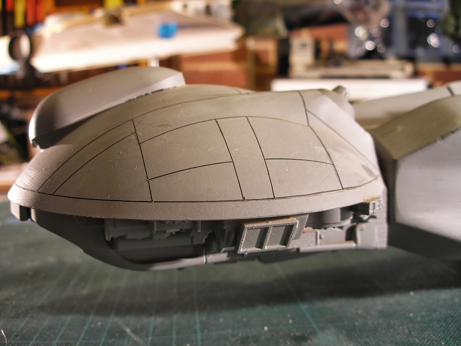
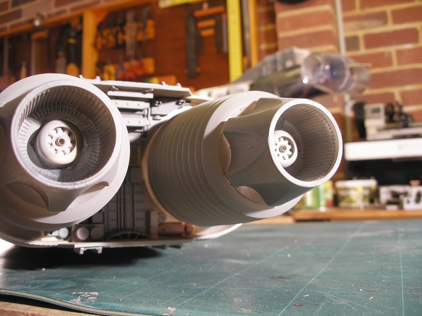
The batteries will be housed inside a mock turbine engine thingy which uses as its base a molded styrene Clinique make up container with a matching lid. The lid will be made detachable to put the batteries in and out. The rear nozzles are from a couple of PVC plumbing pipe couplers. They were glued to a couple of pieces of PVC pipe cut at an angle and in turn glued to the container lid using PVC pipe cement. The container was not long enough to cover the entirety of the batteries so it has been extended with some 2mm styrene sheet and in the picture below some kit part detailing has begun. The batteries slide between two inner walls and push up tightly against a PE foam pad on a lip at the front when the lid is secured and cannot move around. You can also see two pieces of half PVC pipe glued into the end for reinforcement for the lid securing screws to thread into.
 |
| Battery compartment made from a Clinique make up container. |
 |
| Test fitting of the PVC nozzles, the angle looked better than straight. |
 |
| Battery leads exit fom the front. |
 |
| Some Revell 1/25 truck engine parts in white, and 1/32 Mirage fighter parts in grey. |
I still have to figure out a method for making the battery compartment removable, just in case I ever need to tear down the platform at any time. I have also changed the top links of the rear 4 link suspension. I am now using a couple of Traxxas hollow aluminium steering rods which are a bit longer then the original ones I had in there and they are mounted further inboard on the chassis to compensate. This improved the way the axle rotated on suspension compression. I also added a couple of locking links (steering links from a Jato) to the rear axle to adjust the toe-in angle and to stop any hub movement.
I made a mock air scoop for the engine, out of wood covered in 1mm styrene sheet. The scoop section former was made from a short length of dowel cut in half and each side glued to a central block. A textured piece of evergreen siding was stuck to the front of the scoop, sanded flush and then it was wrapped in the 1mm styrene sheet, glued with super glue and clamped until set.
Not shown in these photos, the rounded corners were then coated with car filler and sanded. Then strips of 1mm styrene were inserted into the front of the air scoop using the lines on the evergreen as a guide to make vents. The scoop was then super glued to the top of the engine/battery compartment.
 |
| Nozzles point out and slightly up. |


There is more detailing to do on the engine and a great deal of body work to go on the Tamiya fighter buggy body. I have built a mounting system for the body. The front secures to a small body post from a venom creeper which is mounted on a 6mm thick piece of PVC sheet, which is a brace between the two Jato shock towers. I had to make it in two pieces and then join it as it was difficult getting the bends done accurately at each end with the correct length between. The bends were done using a heat gun, masking of the area not to be heated with some aluminium foil. the end is gripped in a vice up the the bend line, heated until soft and bent using a flat piece of wood trying to be as square as possible and ending at the right angle. This brace will also support the 1/10 Tamiya driver figure I also found on eBay. The rear body mount is a slotted piece of aluminium angle supported on two PVC posts attached to another piece of aluminium angle which is then screwed to two convenient screw receptacles on the body. I used proper plastic screws which I salvaged out of old radios, kitchen appliances and computer printers.
There is a button of turned aluminium on the battery support tray the slot slides under and which retains the body securely (not shown).
 |
| Tamiya 1/12 driver figure. |
Much work has been done up the front in making steering servo support brackets out of 3mm aluminium and blocks of 10mm PVC. The rear chassis had to be lowered relative to the front modified Jato chassis to allow room for the rear most steering servo. Some 6mm spacers were made up and installed. This actually makes the chassis sit more level so it worked out well. A 3mm PVC plate was also installed to house the EVX speed control and the receiver. the EVX control in the photos was an older one that did not have lipo cutoff so I had added a Novak smart stop. I have since replaced that one with a newer one with built in lipo protection and the other one with the smart stop will go into a different model (more about that soon) where there is plenty of room for all the extra wiring.
 |
| Rear steering servo is a tight squeeze. | | | | |
 |
| Front steering servo is mounted up side down. |
 |
| Aluminium M3 threaded spacers support the servo plates. |
The servos I am using are Turnigy 959's built into a billet aluminium case, purchased from Hobby King. They are not the greatest servos by any means but they are extremely strong and relatively cheap if somewhat jittery. They will more than adequately do the job in this application. One odd problem that surfaced is that the EVX esc would not turn on if the small transmission servo was connected to the receiver, its a a Traxxas servo designed to work with this esc. It would work happily if I turned on the esc and then plugged in the servo. To get round this in testing I added a temporary switch so that I can switch in the servo after switching on the esc. It's possible that I need to add an external BEC. The Turnigy servos pull more amps than the Traxxas steering servos used in the models that sport the EVX so they might be pulling it down enough so it wont switch on. I will have to investigate further. Worst case scenario is I have to make my temp switch permanent and remember the start sequence.
 |
| Transmission servo switch. |
The next task is to extend the body work at the front to cover all the exposed guts. The Tamiya fighter buggy body doesn't have any canopy glass either and I want to add some. I am going to have to make a close fitting inside former to attempt to mould some heated thin acrylic. Its going to be tricky so I'm still thinking about how to tackle that one.
Until next time...