About this Blog

This is about the combination of two interests, Radio Control vehicles and Science Fiction models. This blog documents my science fiction spaceship and radio controlled vehicle projects.
Showing posts with label custom build. Show all posts

Tuesday, 14 July 2015

Toy Bash truck part 4

Part1, Part 2, Part 3, Part 5

I wired up and installed the Pololu rc switch using some cut up servo extension leads as plugs. These switches work a treat. They have an onboard flashing surface mount LED that blinks mostly off when the switch is off and mostly on when the switch is on. I covered the tiny board with clear heat shrink to insulate the contacts and to be able to see the led indicator working. The switch defaults to off so when you power up the RC receiver the switch is open and a push of the required control (in this case a button toggle) activates it. Pressing the button again switches it off. The button on the controller of the 3 channel wheel radio is usually employed for such tasks as changing gears on a two speed electric vehicle. If you put a servo on that channel, toggling the switch makes it travel from the equivalent of fully rotated right to fully rotated left. Toggling the switch again has the reverse effect.


I decided to add some rear red LEDs for tail lights. The forward voltage drop on these clear red LEDs is about 2 volts each, I have a 6 volt supply. I used the handy online led resistor calculator provided by the company I buy the LEDs from, to calculate the required resistor for the two LEDs in series at 6 volts. This was a 150 ohm 0.5 watt resistor soldered before the LEDs in series on the positive rail.
The LEDs are mounted in chrome bezels. They are retained in the bezel by a poly ethylene plug which goes behind the LED and just pushes into the back of the bezel relying on friction to stay in place. This is not a very satisfactory system as you can easily push the LED back out of the bezel from the front. I put a couple of blobs of hot glue behind to prevent this from happening. I made a removable styrene cover to hide the wiring underneath. It attaches with a couple of plastic thread screws salvaged from a disassembled toy.


The cockpit console also has a couple of bright white LEDS buried in the cockpit console. The bright whites drop 3 volts each so didn't need any resistor. A model kit part was used as a dual screen console with a bit of thin acrylic (perspex) sanded with fine wet and dry to frost it on the back, glued in behind. Some silver paint was added as a bit of a reflector before gluing in place.


 The console illumination is wired up to the same feed as the headlights.


The screens throw up a small amount of light onto the driver figure. The photo below is a longish exposure and shows it much brighter than in reality.


The driver figure has a plastic thread screw through the chair into his coight to keep him seated.


The Bruder toy's clear plastic windscreen has a wiper blade molded into it. It will get painted or may have to be detailed with some styrene strip.


I also removed the old push switch casing that was on the side of the cab and covered the hole with a kit part or two.


I've added a few more kit parts here and there, mostly at the front.


The lower sides of the cab have been paneled and I added some smaller tanks on top of the larger ones to more fill the truck toy's rear wheel arches.


The piping for the smaller tanks is made from some single conductor electrical wire. It is cheap and easy to obtain from a hardware store by the metre. It is also easy to bend, stays bent, paintable and the pvc outer insulation is able to be securely glued with either thick or thin superglue. It can be straightened by just clamping one end in a vice and pulling the other end. You can get a few different sizes, the two pictured below are 4mm and 2.75mm in diameter. Multi strand wire is no good as it cant hold a tight radius bend. You can sometimes find this stuff in skips on building sites, though with the price of scrap copper these days it is harder to find for free.


There is an empty space on the chassis between the wheels that I am toying with filling with some detail or other. I would also like to do a bit of work to the driver before finally cranking up the primer and beginning the paint process. Mechanically and electrically the vehicle is complete and working.

More soon...

Sunday, 7 June 2015

Toy Bash Truck part 3

Part1, Part 2, Part 4, Part 5


I made up pairs of headlights using some Cree Led aluminium penlight torches I got from China on Ebay. The torches worked out costing about $4 each which I thought was a pretty good deal. They claim they put out about 1000 lumens, I suspect it may be a bit lower than this but they are incredibly bright for their size and only use 1 AA battery at 1.5 volts. They conveniently unscrew at the business end making for a really nice lens and reflector housing, and are easy to mount and solder some wires to.


I wired them up 4 in series thus requiring a 6 volt supply. The battery for the chassis is 7.4 volts so I am employing a Turnigy Ubec which can deliver a switchable 5 or 6 volts at 3amps from any input battery between 2s or 6s which in LiPo battery speak means between 7.4 and 22.2 volts. These 4 penlights are only pulling 1 amp from the battery so there is plenty in reserve.


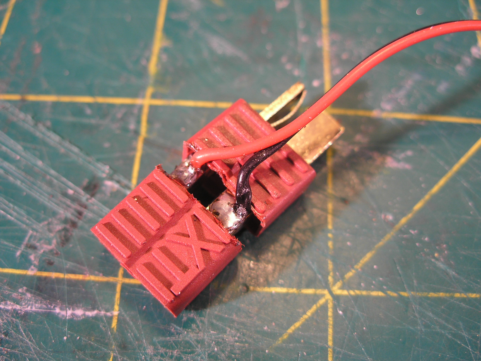
The Ubec is wired to a little adapter which is made from a deans connector plug and socket soldered back to back with the feed wires coming off the positive and negative at the join. The join is then covered with some suitable heatshrink. It is a convenient way of plugging it in between the battery and the speed controller. The lights are wired to a servo extension lead with one end cut off and the appropriate end plugs into the servo style female connector on the output of the UBEC which stands for ( Universal Battery Eliminator Circuit). In the old days of RC you used to have an extra separate battery for the receiver, servos and any other electrical systems it is this legacy battery that is supposedly being eliminated by the UBEC.


The lights are switched by a push button toggle switch mounted on the side of the cab which when painted will just look like a  random bit of detail. It probably would be cooler to make a switch that can be controlled from the transmitter, I am only using 2 of the three channels, but that was laying around in a box so I used it. I like to use whatever is to hand where possible.


The cockpit has been started but still has more work to come. A 1/16 Bruder Toys man sits in the seat. I'm thinking of making some sort of space helmet and converting his rolled up sleeves to be more space suit like.

I made up some tanks from PVC pipe end caps and the next size up pipe which has had a slice removed from its circumference to bring it closer to the outside diameter of the caps. Mounting pieces were made from 10mm foamed PVC, first a hole is made of the same diameter of the pipe and then sections are cut to suit. these slightly domed end caps are getting hard to find. All the new stock at the hardware store have totally flat ends which are not as interesting a shape and I can make those myself easily enough with a disc of flat sheet.


The chassis was shortened at the front to fit the body work that has been built, but yet to be detailed. The olive green radiator looking shape is a leftover spare part from a Tamiya Wild Willy Jeep kit.


More soon...

Saturday, 30 May 2015

Toy Bash Truck part 2

Part1, Part 3, Part 4, Part 5


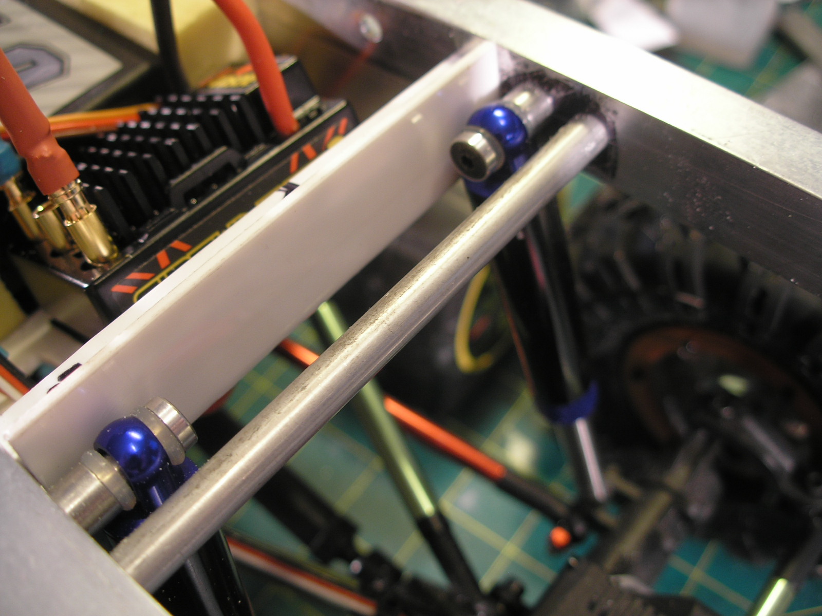
I finally completed constructing the chassis.The creeper chassis plates have been extended by some aluminium angle and channel section. The plates are held apart by some 6mm and 8mm aluminium rod spacers that have been drilled on the mini lathe and threaded at both ends to accept M3 cap screws.


The shocks have been mounted to the link mounting points on the axles with the links moved inboard. A piece of silicon fuel tubing has been inserted as a flexible bush into the hole in the shock shaft to allow some angular movement.


The top of the shocks use the mounting system that is included with the Hot racing shocks. These include a couple of silicon O rings and an aluminium ball shaped insert to allow for angular movement.


A styrene tray was made by heating some styrene with a hot air gun at specific points and bending it onto a wooden form one bend at a time. The trick is to shield the parts that need to remain flat so that only the plastic at the bend area gets heated. It is secured to the frame with some philips headed plastic screws salvaged from some old toy or appliance dis-assembly. The battery, speed controller and receiver are held on with self adhesive velcro. The battery is further sandwiched by some yellow EVA foam cut from a child's learn to swim surfboard.


The speed controller is a Castle Sidewinder 3 which can control both brushless and in this case a brushed motor using two of the 3 connectors. It can also be programmed through a Castle link and USB cable from your computer. It is set to crawler mode which gives a no delay reverse which I like as well as a drag brake at idle. The rear steering servo connects to a Hobby King servo reverser then to a Y connector with the front steering servo giving 4 wheel steering. Due to the 4 wheel steering it has a very small turning circle and is very maneuverable.

Unfortunately as expected the top heavy body tends to flop over to one side or another as can be seen below.


A solution to fix this was to attempt to make a sway bar. After some fiddling about this was made from some 2.5mm piano wire and a couple of small brass plates. Only the rear had enough room to fit this as the motor gets in the way at the front.This turned out to be entirely successful at curing the flop. A small DuBro collar secures the ends of the sway bar into the original shock positions on the axle. The piano wire is pretty old as can be seen by the surface rust, it'll need cleaning and possibly some paint. The hole that the sway bar pivots in has to be slightly bigger, preferably elongated into a slot to allow for the fact that the pivot position does not match the apparent pivot of the 4 link suspension. Its needs some play to compensate.


Here you can see the result of adding the sway bar with a nice level body.


I think the body probably sits a bit too high overall, but there's not a lot I can do about that at this point. I am going to add a bunch of tanks hanging down at the sides which may cure that perception. There is still some more volume to add to the body work at the front so that will help as well.

I completed the detailing of the top and nearly finished the rear.


The yellow part of the rear platform was originally from the top of the cabin of the dozer. The dark grey checker plate floor was from one of the rubbish trucks. The two black shapes that say Dick Smith upside down on them are the servo cases of my very first radio control unit from about 1980. They've sat in a box for nearly 35 years waiting for the right spot to glue them. Got a small amount to add to the back and then finish the front before the grey primer to see how its all looking.

The chassis also needs some paint. The worst part about that is having to dis-assemble and then re-assemble everything over again.

More soon...

Sunday, 30 October 2011

SpinSteer 6X6

Originally I called this a skid steer vehicle but have recently come across a definition which explains that skid steer is when one side is braked and the other side powered to effect a turn to the braked side. In the case of this vehicle, it is more rightly termed "spin steer" because both sides can be powered to effect a turn and one side may even be put into reverse thus spinning the vehicle 360 degrees on the spot. A skid steer vehicle generally has one transmission that goes into a diff. Each side of the diff is a brake which can be alternately engaged by moving the two control sticks so that one side or the other has varying degrees of brake applied thus sending more power to the unbraked side. The Spin Steer vehicle, of which this project is an example, uses two power sources ( a separate motor and throttle per side) which can be independently controlled forward and reverse.

This project has been kicking around for a very long time. I started this when Pro-Line first released the Masher 2000 tyre, which I think was just before the year 2000, so lets say 1999. Again these were the tallest tyres you could get for a 2.2" wheel. They became the original rock crawling tyre which set the form factor for the 2.2 crawler tyre as we know them today, but originally were sold as a monster truck tyre for such rc vehicles as the Traxxas Stampede. of course I was attracted to both their size and the slightly SciFi look of the tread.

I had an idea to build a 6x6 vehicle loosely based on the cool Explosives truck vehicles in Gerry Anderson's Joe 90.


I was also a huge fan of the Banana Splits show as a kid and always wanted one of those amphibious 6 wheeled skid steer atv's they used to hoon around in the shows credits. Since then I have always tended to go for anything with more than 4 wheels.


Originally I was thinking of a shaft drive system with a left and right shaft driving the wheels on each side, with two speed controllers and motors. Some time later Losi introduced a radical belt drive layout for the xx s touring car and I thought something like this might work and be easier than bevel gears to implement.
 This is the Belt layout drawing showing how the belt wraps around the centre wheels pulley with the aid of two idlers. It then goes up over the drive pulley which is the highest circle in the drawing. This drawing also helped me to work out the belt size I would need which turned out to be pretty close to a size that was available. I have since found that the belt slips over the drive pulley in one direction of travel so I am going to have to add another idler to increase the wrap around the drive pulley it will also help as a general belt tensioner. The belts and pulleys are 2.5mm pitch. The idlers are simply two 11x5mm bearings on a stub axle with a collar retainer. It works out that only the smooth back of the belt runs over the idlers. There is no transmission as such, the motors have small 18 tooth pinions driving the biggest spur I could find at 101 teeth. That is mounted on an HPI RS4 slipper clutch on a shaft which then passes back under the motor to drive the 10 tooth pulley. The belt then transfers the drive to the larger pulleys which are 40 tooth.
 Each side is a mirror of the other so one of the motors has to run in reverse. The timing of that motor has been rotated 180 degrees. At the moment I have got two 50 turn crawler motors mounted but may well change to less turns for a bit of extra speed. I was going to run a couple of LRP runner plus reverse ESC's but found they have an annoying amount of delay before reverse kicks in after braking. In this application, so I can Spin Steer I really want  no delay reverse. So I am on the lookout for a couple of cheap no delay reverse ESCs.


 The chassis is a length of 3mm thick 100mm wide aluminium. The blocks which hold the drive and bearings are made from 10mm thick PVC sheet. Its easy to cut accurately on saw table and drill and tap. It also takes super glue very well as long as the mating surfaces are sanded. All the suspension arms, hub carriers cups and axles are Traxxas rear Bandit gear. The cups and axles are the hardened steel universal joint types. The wheels once again are the Venom Creeper wheels. I originally had Tamiya Stadium Blitzer 2.2" rear wheels but after an order of a couple of Creeper wheel pairs arrived, I found the packs contained 4 wheels not pairs as listed. I had these left over so used them instead. They hold the ProLine tyres quite happily and look way better than the Stadium Blitzer wheels. The other thing to note is the suspension arms are molded with about 3 degrees of toe-in built in so all the tyres point inward at the front.

The shocks are plastic bodied front truck types from an unknown Kyosho.
 All of the mechanical aspects of the chassis were worked out and built many years ago. So recently I turned my attention to the body design. After many rough sketches I found I liked the bottom right one the best.

I then drew up a rough CAD version of the outline and made up some bulkhead lines to start cutting material.
I had a box full of balsa wood that I've had for years so decided to put it to some use. The 6mm thick balsa bulkheads were glued up onto longitudinal frames with thin zap-a-gap super glue and then covered with thin sheets and thick planks of balsa to build up the varying levels of the hull skin. A solid chunk of balsa was carved for the nose. I actually went through a couple of bottles of super glue on this.


 The intention is to cover this with thin woven glass cloth and epoxy, making a rigid surface. The balsa bulkheads can then be stripped out of the interior or even left in as it is still fairly light in weight. the Balsa has had a few coats of shellac which gives it that honey colour . Cellulose dope would have been better but I didn't have any at the time. A very lightweight water based premixed interior filler was used in some areas to shape and fill in holes.

 The chassis still needs some top bracing added to prevent flexing of the bottom plate which affects the belt tension. Then the sides, front and rear will be boxed in with styrene sheet and detailing. Some method of battery access and hold down in the chassis is yet to be determined.


 I've got at least another two Sci Fi projects in the works, at least in the very early mostly conceptual stages.
As well as a racing conversion project on the go as well. More soon.


Most Popular Posts in the Last 7 Days