About this Blog

This is about the combination of two interests, Radio Control vehicles and Science Fiction models. This blog documents my science fiction spaceship and radio controlled vehicle projects.
Showing posts with label scifi model. Show all posts

Wednesday, 22 September 2021

Merchant Vessel part 4

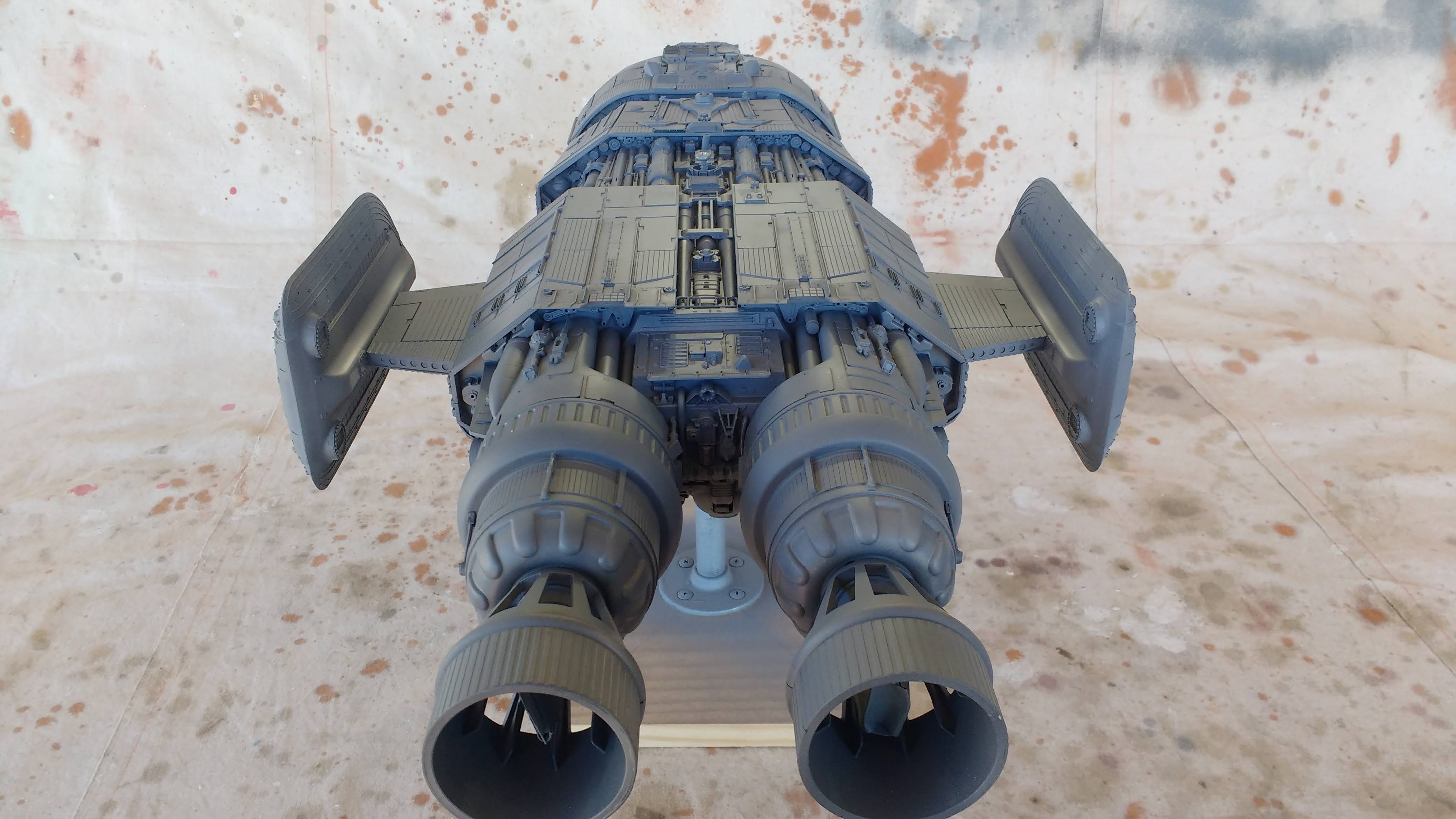
One thing I forgot to add was a hatch so I rectified that problem by modifying the command section with an underside door/ramp on each side. The picture below shows it on the model which is mounted  bottom side up so the door is shown below upside down.


 After taking care of that omission and adding a few small details to the landing pads it was time to complete the application of grey primer. The result of which is shown in the following series of pictures below.


The picture above shows the starboard door which would theoretically hinge down forming a ramp.


 Next task is to design a paint scheme.

At this stage I am intending that the inset detail areas and engines will remain dark grey with the command section, skinned hull areas and wings predominantly green with red markings.

Thanks for looking.

More soon...


Friday, 5 March 2021

Moon Bug part 7 - Completed.

 Its been 5 months since the last post on the Moon bug and I have not been able to do any modeling for some time but I have finally managed to finish the Moon Bug project.

Last time the model was at the primer stage, so the first job was to devise a paint scheme. As is my process these days I took a grey primer photo into photoshop and fiddled about until I came up with something I liked.As the vehicle has a whimsical comic book outline I wanted to do a colorful paint job to go with it. This is what I came up with.


 I then decided to design up and make some decals to add to the graphic nature of the finish. These i designed in Inkscape which is a free open source vector graphic editing program. I have always liked the graphic elements that Chriss Foss would apply to his gouache painted spacecraft book covers of the 1970s'. Referring to my Chriss Foss art book I availed myself of some of his genius and some of the decals do bear a very strong resemblance to his work. Here is the decal sheet.

One of the problems with DIY decals is that inkjet printers can't print white so if you want white in your decal you have to use white decal paper. That then means the carrier is white and you have to carefully cut around each decal to remove the extraneous white around the edges. Of course you can use clear decal paper which means you don't have to be as precise when cutting out the decal as the borders will be clear and will not be visible once applied but any white areas on your design will come out clear. If it is a big decal you can paint a white area where you want the white bit to be but for small decals I think it would be too hard to get the white painted areas that accurate.

I printed onto white decal paper and once cutting out the decals and applying them with much setting solution found that little white edges showed up which wasn't exactly what I wanted. I have since found some online tips for using white decal paper, where the edges of the decal should be coloured with a permanent marker to get rid of any white bleed once applied. Too late for me but a good idea for any future project that needs custom decals.

Paint was car paint from touch up spray cans with varying shades mixed up once decanted into airbrush jars and airbrushed on. Weathering was my usual method of a wash of Tamiya flat back diluted in much methylated spirits, wiped off with a metho soaked rag in the direction of the required streaks and drybrushing with white students acrylic. I then also added some oil paint colour modulation and a dirty brown pin wash.

One of the things I tried out on this model was painted panels lined out with a fine permanent marker pen. Models from Terrahawks recently came up for auction with accompanying photos and they had a surface that used a similar technique to very good effect. 

Photographically it seems to work just fine but in person, to the naked eye the conceit is all too obvious. My conclusion is that I prefer to have panels that are in the very least scribed into the surface if not actually separate from the underlying surface and glued on individually. I prefer the way light hits an actual edge with both a highlight on one side and a shadow on the other.

One thing I added to the model was a couple of dummy whip aerials on the top blisters at the rear. They are made from bicycle gear cable with a couple of plastic kits parts for a mount and a termination at the top. They should wave about fairly realistically when the vehicle is in motion.

I also swapped out the Kyosho springs on the shocks for some much stiffer Arrma springs part number AR330417. These are extremely stiff, fit the Mad Crusher shocks and have no trouble holding up the heavy body. If anything they are a little too stiff at 317gf/mm (17.75lb/inch or 3.109 N/mm) or but so far I haven't found any other springs the right length (75mm) and diameter (ID16mm) with a slightly less stiffness rating. The springs came with a chrome finish so I sprayed them matte black to make them a little less obvious.

Finally here is the finished model.


The next project up for completion is going to be a spaceship. In fact it will be one I started way back in 2013 and haven't touched since. Here is the first part of the project from 2013 - New Spaceship Model part 1.

In fact I need to come up with a better name for this spaceship as New Spaceship Model is pretty lame and considering it was started in 2013 it isn't all that new any more. If you have any suggestions for a decent name for the project please leave a comment.

Thanks for looking...

More soon...


Sunday, 19 January 2020

The gestation of a project.

The following is a an example of how a project of mine starts from a random idea to a possible physical reality. I do a lot of these preliminary processes on project ideas and there are many factors that determine whether the idea becomes an actual project and I start posting about them.

I find I have to really be surprised by how a project is coming together for me to push through to completion. It has to start looking as good or preferably better than what I imagined when I started for me to ignore the many distractions along the way. As soon as a project doesn't quite measure up to the image I held in my mind's eye at the very start, my devotion starts to slip away. If I then find I don't really like what I have done I lose interest and the project sits abandoned.
In the case with this body it still has something I like about it and I realised that I had not followed my own thumbnail closely enough. Somewhere along the way I had lost what it was I liked about it in the first place. The main problem was the front and those side windows which originallywent all the way down. After I made the front window I filled in the lower part because it didn't fit with the narrower aspect of the front window. This is due to the fact I never roughed out the front in a sketch. When I look at the thumbnail now I can see that I meant the front window to be as expansive as the side windows. In fact I imagined it going up over the roof stopping inline with the angled back of the side window. Narrowing  the front window had ruined the proportions.  I also constructed a much larger bevel along the top edge than suggested by the thumbnail. It no longer had the character that appealed to me to start with.


Sometimes with the passage of time a project can be re-evaluated and a spark of an idea to rescue it from abandonment surfaces.


I have been looking at possibilities over a long period for the rejected body for the creeper 6X6 project which is just lying around.
The picture below shows it on that Creeper 6x6 chassis and I just didn't like the way it sat, for me the proportions were all wrong, the wheels were too small and the chassis too long.


I have tried it on a few different  four wheeled chassis with various sized wheels and it just never seems to look right.
The the other day I got the idea that maybe it would sit better on an alternative to tyres.
A quick photoshop session then ensued to rough out the concept and see if it had legs, or more specifically tracks.


Now to my eye that's much more like it, I think it sits well on those tracks which are from a M113 APC. I also changed the nose slightly  to hint at a larger area of glass to the front which is a big improvement. It was time to move to an experimental phase as there was a big technical question to be answered.

Can I find some tracks that would do the job. I considered various Heng Long Tank chassis and tracks at 1/16 scale but they are too small to look right. Can I get a larger scale set of tracks? I found the very thing on Ebay, metal 1/8th scale tracks with drive sprockets to fit... but they cost way more than I can afford.
The next obvious question is can I make my own tracks that will be strong and work?
It was time to try an experiment. The first step was look at various tank track links and determine the simplest solution to engineer with my meager resources. Most of them are very complicated castings but I remembered the Tamiya Leopard metal tracks and how they easily go together from simple parts and decided to upscale that concept.
Next step was to rough something out in CAD which I did and decided it was too big so I drew up a smaller version you can see below.


The material I chose was grey PVC sheet. It is a material I am familiar with and more importantly I had some in 6mm which actually measured out to 5.6mm thick which is better for me. Sliced up some strips on the circular saw and chopped them off on a mini docking saw. Drilled holes and inserted brass brazing rod pins.


The pins are 2.4mm in diameter so the track pads were drilled 2.5mm for clearance. The cleats on the end of the pins which tie them together were drilled 2.2mm so the pins are a press fit and hopefully wont come off, a drop of thin superglue should do the trick if they look like loosening up.


The test showed that it would be possible to make them provided that the drilling was precisely spaced and square. To achieve this a jig would be required to make the job easily repeatable and accurate. It would be a tedious job as I estimate I would need around 124 links to make two tracks. There are 5 parts and two pins per link making 868 parts with 1240 holes needing to be drilled.
I was also thinking of adding a rubberpad to each of the track pads, superglue would do the trick here as it works very well on both rubber and PVC.

While I think it wouldn't be too difficult to make the idlers and the road wheels and even the suspension arms, there is the question of making the drive sprockets which would be another story in itself.

Will this idea proceed? There is a chance it will as I am enthused by the concept but I have a few other projects requiring attention at the moment so we will see.

Thanks for looking.
More soon...

Wednesday, 25 September 2019

Resilient cruiser part 2

Its only been 3 years since part 1 (September 2016) but I am back on the Resilient cruiser.

See this blog entry from 2013 Unfinished Old Spaceship model Part 1 for the background story to this project.

As it happens the Resilient criuser part one page is the second most popular page on rcscifi.
Why that is, is a mystery to me but the photos feature on a lot of Pinterest pages which result in clicks coming from Pinterest going to the page.

I have started to detail the upper surface.

I was given a box of old broken transformer toys which took me a long time to disassemble into their constituents keeping the styrene and ABS parts (as well as the screws) and junking the rest. You will see a few of those bits show up on this project.


I also started on the Com tower using one of the small battery powered push light domes for the dish.
I have some other smaller dishes to add to this tower in keeping with the Ep 1 Radiant VII influence.


More soon...

Part3 is here.

Most Popular Posts in the Last 7 Days