Almost 10 years ago in 2015 I did a post called Giant Tyres and DIY PVC wheels. In that post I showed a method of making some beadlock wheels out of PVC plumbing parts for the super massive Interco Super Swamper 40 series tyres from RC4WD. The tyres are 250mm in diameter (10") and weigh over a kilogram each and I had 3 pairs, planning to make a 6x6.
The tyres in question are on the left with Proline 3.8 trenchers in the middle and Imex Jumbo Maxx (3.2) Swampers on the right.


Later that year (2015) I did a post about a test rig to see if I could make a motor per wheel set up work using a Traxxas EVX brushed speed control running three motors per side. I found that it did indeed work using cheap 540 geared motors using Imex Jumbo Maxx tyres and Losi ATX tyres with a 500rpm (at no load) gearbox. I determined that due to the increased circumference, 1.4 times greater, the Interco Super Swampers would need gearing down somewhat.


Over the last 9 years I have pulled the tyres and wheels out of their boxes and then promptly put them back in again. There have been a number of body concepts and chassis suspension ideas all eventually rejected. I had another false start when a purchase of a set of gearmotors turned out to be too weak finally much later I settled on some more 540 brushed motors paired with 160rpm gearboxes that seemed to have the required torque. Last year I made some progress on the chassis of another 6X6, the suspension of which which helped solidify the design for this project. I also had bought a cheap 3D printer and got used to thinking about making more complex parts for my extremely low budget projects.
In 2024 I finally felt I had the confidence to tackle probably the largest RC scifi vehicle I will ever attempt.
First thing I did was build a prototype suspension arm and figure out the shock position required. I am using Traxxas GT shocks from a Traxxas Summit. These are designed to take the very large leverage of an inboard shock arrangement so are good for a very heavy direct suspension at the expense of considerably reduced suspension travel.


I figured the shock would work at about 30% percent of the distance from the pivot point to the wheel centre. This gave me enough support to hold up what will inevitably be an extremely heavy model, and still have a reasonable amount of suspension travel. Moving the shock further towards the pivot will result in more travel but with less weight capacity and vice versa. Its a bit of a balancing act and I can only judge this by feel rather than by any advanced engineering skills or math.
There is a 10mm flange on both sides of the chassis wall with a 10mm rod holder gripping a short 10mm aluminium shaft. The flanged bearings have grub screws to prevent the suspension arm sliding out. The rod holder is mated to some rectangular 20mm x 40mm aluminium tube via a 3D printed part. All the 3D printed parts were printed in PETG and designed to be an interference fit inside the aluminium tube. They were secured with countersunk bolts and nylock nuts. The final red parts were printed at home on my cheap Anycubic Kobra Neo whereas the black prototype parts were printed on the Prusa MK4 at work. The Prusa prints are generally much smoother and certainly a lot faster to print but the machines cost considerably more to purchase.


At the other end is another 3D printed motor holder which clamps onto the motor can. These particular motor gearbox combinations came with a mounting plate at the front which is also attached back to the 3D printed motor holder with M5 threaded aluminium spacers. The wheels are mated to slightly modified Traxxas 17mm hubs with a grub screw securely loctited against the flat on the gearbox shaft.

With the suspension sorted out I started on the chassis proper and drew up a side layout in CAD.

Then I needed a cut outline as I was planning to build the chassis out of two layers of 6mm Foamed PVC. Usually I do this by hand as described many times in my projects but in this instance made use of the CNC router I have access to at work. All the mounting holes for the suspension bearing flanges were cut at the same time. It would be nice to have one of these at home but I do not have the space or crucially the cash.


The layers were glued together with super glue after first roughing up the mating areas with coarse sandpaper. The rest of the chassis was built from the same material making a long open box with a 45 degree angle at the front and a 15 degree angle at the rear.


I needed to finalise a body design. Rummaging through my large object parts stash I found a large acrylic drinks cooler and a purple acrylic bowl. both interesting shapes made from the right sort of plastic and found in charity shops a few years ago. These objects triggered the rough thumbnail design below.

The acrylic drinks holder was designed to hold a pile of ice and keep your drinks cool. It was made with an extremely thick base that needed to be removed. This I did by chain drilling a series of holes and then knocking out the massive lump of plastic. The jagged edge was then sanded out using a drum sander in a drill. You can see one half of the purple plastic bowl in the chassis pictures above.


This was then split in half to become the two sides of a transitional neck section of the body.
I didn't do any cad for the main body structure I just drew up the shapes for cutting out in the Foamed PVC Itself. I decided to make two skinned sides and then join them together with bulkhead frames after the sides were done. The bulkhead frames were made from 6mm foamed PVC.
I started with the side profile frames cut from 3mm foamed PVC. I used material from old signs they were throwing out at work for a good proportion of the construction. This is the reason they have odd graphics on one side. The biggest aggravation from using this sign material was that the printed graphics were covered with a clear protection sticker that I had to laboriously peel off as it prevented the superglue from adhering properly. It was extremely challenging to remove and then it left old sticky gum all over the surface which then was another nightmare to clean off. I used a citrus based gum remover and even that had a hard time getting it off.

The corner radii were drilled out using a 20mm step drill and then the waste material was cut out using an OLFA knife and steel ruler along with a jigsaw.


This side structure was then skinned in 3mm foamed PVC with a few darts (wedge shaped cuts) here and there to make it conform to the compound curved shape. Super glue works extremely well on PVC though I still rough up any glossy mating surfaces.
The two sides were then brought together with more 6mm bulkhead frames. The body sits on two rails of 10mm PVC on the inside of the sides which overlap the chassis by 10mm.


Strips of 3mm foamed PVC were then glued as doublers 3mm below the top edge and the top surface filled in with more 3mm sheet foamed PVC. The front cockpit section was cut into a curved shape.


After toying with 1/35 scale I decided to scale this model at 1/24 scale which still makes it a behemoth.
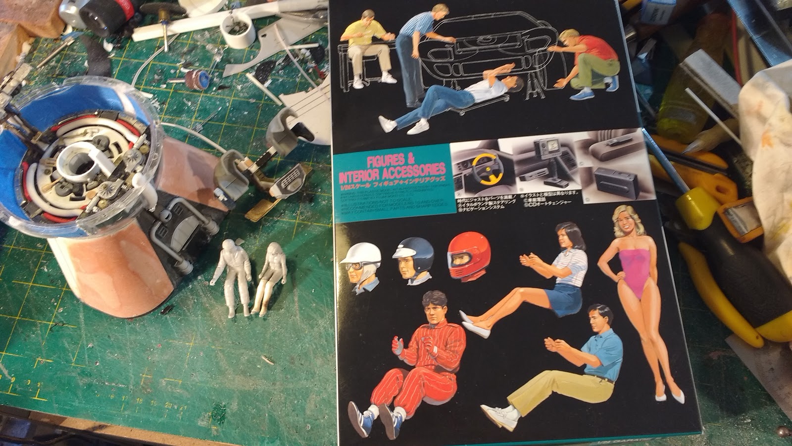
At the moment the body measures 1130mm (44") long and 600mm (24") wide. I put some seated 1/24 figures roughly in place for scale.


There is still a booster board to be added to power the 12 volt lighting circuit and a pololu switch to remotely switch the eventual lighting on from the transmitter. The booster board takes 7.4 volts from one of the battery's balance plugs and boosts it to 12 volts losing some current in the process but as all the lighting will be LED strips it wont matter a bit.
I also added a pair of strong magnets to both the front and rear of the chassis and to the body as a hold down system. We will see if this is sufficient in due course.


I wanted to test out the chassis so proceeded to wire up the 6 motors and two ESCs, built a battery section housing the four 2s lipos and installed the receiver.

I 3d printed some grommets to feed the two 14AWG silicon wires through the chassis walls.


The Traxxas EVX ESCs I am using in this model are the older versions without a LIPO cut off feature. To surmount this omission I have added a Novak Lipo cutoff in line with each ESC. Channel two on the receiver drives the left side wheels and channel 3 drives the right side. The right side ESC also provides the BEC to power the receiver. This means the left side Novak Smart Stop has had the red wire carefully removed from the plug so that only the single BEC is sending power to the receiver.


Thanks for looking.
More soon...