Part1, Part 3, Part 4, Part 5
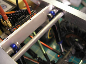
I finally completed constructing the chassis.The creeper chassis plates have been extended by some aluminium angle and channel section. The plates are held apart by some 6mm and 8mm aluminium rod spacers that have been drilled on the mini lathe and threaded at both ends to accept M3 cap screws.
The shocks have been mounted to the link mounting points on the axles with the links moved inboard. A piece of silicon fuel tubing has been inserted as a flexible bush into the hole in the shock shaft to allow some angular movement.
The top of the shocks use the mounting system that is included with the Hot racing shocks. These include a couple of silicon O rings and an aluminium ball shaped insert to allow for angular movement.
A styrene tray was made by heating some styrene with a hot air gun at specific points and bending it onto a wooden form one bend at a time. The trick is to shield the parts that need to remain flat so that only the plastic at the bend area gets heated. It is secured to the frame with some philips headed plastic screws salvaged from some old toy or appliance dis-assembly. The battery, speed controller and receiver are held on with self adhesive velcro. The battery is further sandwiched by some yellow EVA foam cut from a child's learn to swim surfboard.
The speed controller is a Castle Sidewinder 3 which can control both brushless and in this case a brushed motor using two of the 3 connectors. It can also be programmed through a Castle link and USB cable from your computer. It is set to crawler mode which gives a no delay reverse which I like as well as a drag brake at idle. The rear steering servo connects to a Hobby King servo reverser then to a Y connector with the front steering servo giving 4 wheel steering. Due to the 4 wheel steering it has a very small turning circle and is very maneuverable.
Unfortunately as expected the top heavy body tends to flop over to one side or another as can be seen below.
A solution to fix this was to attempt to make a sway bar. After some fiddling about this was made from some 2.5mm piano wire and a couple of small brass plates. Only the rear had enough room to fit this as the motor gets in the way at the front.This turned out to be entirely successful at curing the flop. A small DuBro collar secures the ends of the sway bar into the original shock positions on the axle. The piano wire is pretty old as can be seen by the surface rust, it'll need cleaning and possibly some paint. The hole that the sway bar pivots in has to be slightly bigger, preferably elongated into a slot to allow for the fact that the pivot position does not match the apparent pivot of the 4 link suspension. Its needs some play to compensate.
Here you can see the result of adding the sway bar with a nice level body.
I think the body probably sits a bit too high overall, but there's not a lot I can do about that at this point. I am going to add a bunch of tanks hanging down at the sides which may cure that perception. There is still some more volume to add to the body work at the front so that will help as well.
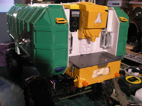
I completed the detailing of the top and nearly finished the rear.
The yellow part of the rear platform was originally from the top of the cabin of the dozer. The dark grey checker plate floor was from one of the rubbish trucks. The two black shapes that say Dick Smith upside down on them are the servo cases of my very first radio control unit from about 1980. They've sat in a box for nearly 35 years waiting for the right spot to glue them. Got a small amount to add to the back and then finish the front before the grey primer to see how its all looking.
The chassis also needs some paint. The worst part about that is having to dis-assemble and then re-assemble everything over again.
More soon...


No comments:
Post a Comment