Pages

Wednesday, 29 October 2014

Tools part2

Here is another look at some more of my most used tools used to make holes of one sort or another, starting with my lathe, the tiny but very useful Emco Unimat 3.


I use this all the time for turning up spacers, drilling out links, tapping holes in the end of link rods etc. I got this second hand in 1990 for $400 Australian dollars which at the time I thought was pretty steep. It is very well made and the only problems I had was constantly breaking the rubber O ring belts and they were pretty hard to get and expensive to replace. For a long while I was making my own belts from that flexible plastic tubing used to push into a slot to secure flyscreening material in its frame. It was easy to heat up the two ends with a heat gun and push them together to make a belt. This would periocically break and have to be re-joined. Now I have discovered that there are people who make very good quality urethane belts and sell them on ebay at a decent price. The urethane belts are very hard wearing, last for ages and do a very good job.
To get a tap to go in square and true to a link rod or spacer I remove the belt and turn the spindle by hand with the tap in the chuck and the tail stock free to slide.

Bright Orange urethane belts. Note the belt that goes to the idler pulley does not actually need to be there, its not actually doing anything in this arrangement. At this speed setting the spindle is being directly driven from the motor pulley

As I have mentioned in a previous post it would be useful to get a 4 jaw chuck, in fact it would be good to get a bigger lathe as the size is really rather restrictive in what tasks you can carry out, for instance the biggest drill the chuck can only take is only 8mm but it is certainly a lot better than nothing. The other thing on my wish list is a small milling machine. It would allow me to make a lot of parts I currently buy and adapt, from scratch.

Probably the most useful tool is my drill press. It is a small 5 speed one made in Taiwan that I bought in about 1984. The only problem I had with it was the plastic depth stop bracket broke after only a year or so. I used it for many years without that facility, finally getting around to making a new one from PVC this year (almost 30 years later). It is still using its original v belt. Next to it is my 3 wheeler band saw, bought around about the same time and also made in Taiwan. Similar to the lathe this ones rubber tyres and belt wore out and have been replaced with urethane tyres and belt again provided by vendors on Ebay. Just a couple of months ago a tiny spring in the power switch broke. I took it apart, luckily a suitable stand in was found in my junk springs box and its back up and running again.


The following picture shows a pvc ring being made with the drill press, the central hole being made by a speedbore bit. This ring was then cut into two and further shaped to make the shock link adaptors for the Moon Bus project.


The next rotary cutting device I have found very useful over the years for making plastic discs and cutting large holes. The cutting bit can be rotated in the holder 90 degrees to cut either an inside hole or as shown here an outside edge making a disc. It leaves a 45 degree bevel on the waste material when cutting a hole which can be used as an interesting detail. The drill is run on its lowest speed when using this with a gentle feed and you need to keep your fingers well out of the way, preferably clamping the workpiece.


The following are the rest of my hole cutting tools. The step drills work really well on plastic and aluminium sheet. I have recently added to the step drill with a much larger one that can go up to 32mm, not shown here. Also not shown are three twist drill sets Metric 1-13mm in 0.5mm steps, Imperial 1/16 - 1/2 inch which rarely ever get used and another metric set 1-5.9 in 0.1mm steps a most useful set. there is also a drum sander that I often use in the drill press.
For disc cutting in thin styrene sheet I use an OLFA circle cutter. The trick is to turn it backwards to scribe a groove into the plastic. The thin sharp point in the forward direction tends to want to waver whereas running it backwards it stays on track.


That's about it for hole cutting.
tools part 1

Tuesday, 28 October 2014

Moon Bus part 1

Here is another project that has been commenced, I'm calling it a Moon Bus. Below is the rough design thumbnails. The design started with the tyres, I have had a set of Imex truck pull Clodbuster tyres sitting around for quite a few years, but have never had any rims to fit. The other trick is that these tyres did not come with any foams. One of my random Ebay trawls came up with a really cool set of rims that would be perfect for these tyres and a sci-fi flavoured project...

Moon Bus design thumbnails.


 The rims are an older version of the RC4WD Clod beadlocks which are no longer available. I think you might still get a later revised version with a seperate interchangeable hub. These have a 14mm hex socket and came with some splined 14mm hexes designed to mate with the Tamiya Clod Buster splined axles. They are really beautifully machined and this set does not appear to have been used much, if at all. The front beadlock rings have a number of cosmetic non-functional very short cap screws with 8 functional ones like the back rings. The beadlocks actually completely seal the tyre so they remain effectively pumped up without any foams in place. They have sat around like this for several months now and still have not deflated. They have a massive machined hub which screws in to hide the wheel nut and the rims are really thick and quite heavy.

The two chassis plates I made from 3mm aluminium sheet, drawn up in Delta Cad, printed out, spray glued onto the aluminium and all the inner hole radiuses were drilled out. I then used a scroll saw to cut out all the holes finishing up with hand filing.  The blades for the scroll saw although designed for wood will cut thin aluminium but dont last as long. I went through quite a few. These were made way back in 2002. The shape being inspired by the Tamiya TXT-1 monster truck. I was planning to build a monster truck at the time but it never got very far.


My original CAD drawing from 2002.

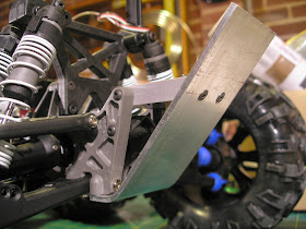
The plates have been cut and shunted a bit. Originally the idea for the monster truck was for the battery to sit low down on the extended sides, these have now been chopped and moved to support the upper links. The axles are a set from a Venom Creeper that have a manually switchable diff lock. The transmission is from a Creeper as well. It does not have a slipper clutch which could turn out to be an issue. The lower links are Axial machined high clearance links just because they look cool and I already had a pair which I got to try out on the GrassHopper project for which they didn't turn out to be suitable.
It took a lot of fiddling to sort out the shock placement. They have ended up pretty much in the monster truck vertical position. They have to be able to push up the heavy body without it flopping over to one side that the usual angled crawler shock position encourages. The shocks are a set of Hot Racing oil-less ones that rely on air damping. They look cool but I am not all that convinced of their efficacy.
The Creeper axles have a really annoying angled shock link mount so I had to make up a set of PVC adaptors so the shocks could mount vertically without binding. They are captured by some vinyl fuel tubing bushes which permit flexibility of movement. The first set I made were straight but this meant the shocks were too tall so I made some curved versions. The curved versions restrict the steering throw a bit but as this vehicle has 4 wheel steering it may not turn out to be a problem. As yet I have not tested it. The second hole was added in case there was a need for a sway bar set up.

Discarded straight adaptors.

Revised curved adaptors.


These were extremely fiddly to get right. It would have been sensible to have just used Axial axles except that I like the ability to use a proper unlocked diff given that this is not really a hard core rock crawler.
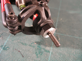
The other difficulty was getting those beadlocks to mount up. I needed some form of widener to get enough clearance so the rims did not foul the knuckles and the links especially when turned. I ended up getting some Integy 12mm to14mm hex adaptor wideners. They came with two sets of barrel nuts, short and long. The long ones were not long enough. Those beadlocks have about 10mm thick hubs whereas most plastic wheels have only about 3 or 4mm thickness. The project ground to a halt for many months at this point while I contemplated what to do. In the end I made my own barrel nuts from some 6mm bolts. I got some 60mm in length M6 bolts and cut off the thread. The remaining bolt shoulders were drilled out and tapped M4 to fit the axle thread and the beadlocks had to be drilled out slightly to fit the 6mm bolts which are actually only 5.8mm in diameter. I have a set of metric drills that go from 1 to 5.9mm in 0.1mm steps, very useful for tapping and clearance hole sizes.


I think the Integy wideners are too wide, if I could find something that has a much smaller offset and a 14mm hex I would swap them out. It would also reduce the amount of tyre scrub when the steering is turned. In an attempt to shorten the offset as much as possible I used machined down Axial narrow aluminium hexes designed for 1.9 sized wheels.

A start has aslo been made on the body. A wooden frame has been cut and assembled. It comes out at about 1/16th scale. I need to get some suitably scaled driver figures. I think the Bruder toy range of figures may fit the bill.


The body is held on by 4 X M4 cap screws which pass through holes in the chassis and thread into plates screwed to the wooden frame.


One of the servos has a servo reversing lead so the 4 wheel steering works correctly in opposite lock.
I need to make up a battery tray and mount the electronics, then I can test it out...more later.

Part 1, Part 2, Part 3, Part 4, Part 5, Part 6, Part 7

Monday, 27 October 2014

Space Truck 8X8 part 1

Fairly typically I have started a new project ( actually quite a few) without completing the old ones. I cant help myself, I do so much thinking about a model over a long period of time that once it is underway my mind starts to wander and think about the next one. A new idea can be sparked by some left over parts from some previous experimentation, or by something seen on various forums. It sometimes takes a while to amass the parts required and come up with concept thumbnails that lead to a design I like, and at other times I get obsessed and I just have to start now.
This one is the latter, the chassis at least came together relatively quickly.
As  the title states it is an 8X8, based mostly on traxass E-maxx parts. I got this idea from looking at this modellers site http://www.krohpit.ru/2012/10/8x8.html

My version is nowhere near as sophisticated and although much simpler mechanically, has not been as straightforward as it looks on first glance.

This is the thumbnail sketch I settled on for the body.


I then did some preliminary modeling to scale in Autodesk Maya to refine the design.


Then using the side view picture I knocked up a full size cad drawing in DraftSight.


I purchased a pile of E-maxx parts off Ebay, some new and some secondhand from a guy who also had some wheels and tyres he wanted to offload cheap. 4 of them were traxxas Summit wheels and tyres. I figured I may as well use these on this model and got 4 more new ones, again from E-bay.


While the wheels themselves are pretty solid ( fake beadlocks) and relatively cheap for their size from the E-bay parts dis-mantlers, the Canyon tyres are extremely thin walled, like a thick rubber glove. In consequence they do hug the terrain well but by all accounts are easily ripped on sharp stones. In this case they will probably do fine, time will tell.
Here is the chassis so far, it is big, bloody big... overall 900mm long. The body will add to this length eventually.


It is powered by a DeWalt brushed 14.4 volt motor via a EVX2 speed controller. The transmission is my usual choice, namely the Summit two speed for that low speed, high torque capability. We will see if this will be enough to move this beast, I have not as yet tested it. The two front sets of wheels are steered.


The transmission speed selection servo is an old mini futaba that I have had for years sitting in a box. I purchased this servo from an aborted movie production in 1987. The movie Total recall was originally being made in Australia, in Sydney by Dino Delaurentis and going to be directed by Bruce Beresford. Then the '87 stock market crash happened and the movie got canned after about 6 months worth of visual effects miniatures had been built. I had some friends who were working on the models for the film, they had a big firesale and I purchased a couple of the incomplete vehicles. One was  a 6 wheeled rig made from Thunder Tiger Silver Fox parts and one was the Tamiya 1/16th RC Leopard tank ( which I stupidly sold many years ago), the servo came as part of these.


The aluminium top plate has had a small recess milled into it to clear the spring lever for the two speed shifter. I don't have a milling machine and only a tiny Emco Unimat3 lathe. For this task I use a Dremel bit that looks like a tiny 3 flute end mill in my small 5 speed drill press and very slowly push the plate around by hand nibbling away at the metal. It is not the most ideal set up but it's all I have. I would dearly love a small milling machine and a bigger lathe but at the moment they are just a bit too far out of reach for my meagre purchasing power. The Unimat 3 which I have had since 1990 is very useful for making links and spacers but cant really handle much larger tasks. I don't even have a 4 jaw chuck to hold square items but its better than trying to file parts mounted in a spinning drill and way better than nothing.


The maxx steering post has had to be slightly modified so the lever comes off at 90 degrees to the original position. It is made from Pvc and is super glued to the servo saver part. I hope it stands up to use. If it doesn't I will have to engineer something stronger. The front most steering arm is slightly longer than the inner one. It has a hole further out from the centre so that the front most steering turns slightly less than the inner. The inner set of front wheels turns on a smaller radius then the outer set so the slightly smaller movement that results should compensate. Note that I did not actually calculate any angular mathematics for all this, thats just not my strong point, I just basically winged it. I am pretty sure however, that this vehicle is going to have a relatively large turning circle.


. The diffs  at each end are Maxx diffs, but the two inner ones are modified Revo diffs. Unlike the Maxx diffs which have a left and a right side, the Revo diffs have a back and front half so it is easy to get a second set of diff cases and bolt two front halves together along with a second pinion gear and bearing. This makes a diff that has an input and an output pinion for attaching to the driveshafts that lead to the transmission at one end and the end diff at the other. There is a little lip on the diff cases that has to be sanded off so they mate flush. Then there is a big job in dremeling out the Maxx diff bulkheads to fit these Revo diffs. This is the hardest part of the conversion. I had to also make some new pvc parts to hold the Revo diffs in the Maxx bulkheads so they don't rotate, much like the  transverse collar that comes with the Maxx diffs. It also helps that the Maxx and Revo diffs have the same ring and pinion gears so the axles all turn at the same speed.
The other catch is that the front diff bulkheads are designed to be mounted angled up for front castor purposes. In this case they are mounted flat and the transverse diff collar holes expect this. I had to make a new PVC block to act as a transverse collar holding the diffs at a corrected angle. Originally I made a large block that bolted to the bottom chassis plate but this ended up fouling the steering bellcranks. The blocks had to be removed and remade to bolt to the top plates. That is why there is a couple of unused countersunk holes in the front bottom chassis plates. It is really a very tight fit around the steering beelcranks with a thick drive shaft running through the middle of it and the locking the diffs in place. It was quite a fiddle to sort out. This is one of those occasions where a milling machine would have been handy. I could have made entirely new bulkheads that alleviate all the problems that adapting existing parts throws up.
You have to remember to alternate the ring gear side of the diffs as you go down the chassis so all the axles turn in the same direction, otherwise if they line up all on the same side some of the axles will be going forward while others are going backwards.

Maxx diff at both ends.

Modded Revo diffs in the middle.

Aluminium brace made up to clear the drive shaft for the inner rear diff.

 Various reinforcement blocks of 10mm Pvc have been made to tie all the bits together.
I am planning to build the body out of PVC foam sheet to try to keep the weight down a bit.
Next to go is the battery and ESC mounting positions, then I can test it out...

Sunday, 26 October 2014

Explorer part 4

Some progress has been made on the detailing of the Explorer hull.


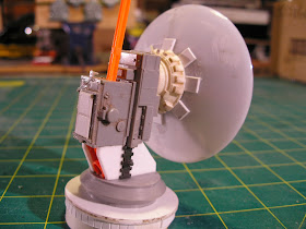
The black bits are 1mm styrene sheet. the corner triangles are 2mm styrene and the struts are pvc foam 3mm thickness. You can also see a communications dish made from the dome of a battery led push lamp from the hardware store as well as some 1/48th aircraft carrier service equipment kit parts among others. The probe is made from bits of brass. I think the end was turned up for a model boat navigation lamp. Its been sitting in a box of brass bits for years.


The bottom is a piece of grey pvc secured with a screw to a disc of 2mm styrene which is glued to a pvc tube cut at an angle to match the slope of the hull. This tube is then press fit on to a smaller piece of pvc tube glued to the base made from the upper hull of a Tamiya 1/35 Panzer Kampfwagen II kit.
It can be manually rotated into a new position but is not motorised. It is easily removable to prevent damage while still working on the model. The bright orange stalk is a piece of an air restrictor out of a Nerf blaster... no styrene is wasted.


The rear of the dome is a cast part from a set of molds I made back in 1988. Way back then I stuck a whole pile of  kit parts to some perspex blanks to use up some old silicon mold material thinking they may come in handy one day. The molds have sat in a plastic bag collecting dirt for the last 24 years. I got myself some Barnes Easy Cast which is a 2 part urethane casting material which is a clear, water thin, liquid when mixed and sets in 10 minutes into a white solid which is easily sanded. It is really terrific stuff. Unfortunately the quality of the molds is not the greatest and the silicon is now slightly more brittle than it was 24 years ago, but it does the job. There is a layer of dirt stuck in the surface of the initial batch of parts but the primer should cover that. The second pull comes out clean.


I have also completed wiring in the lighting. There are 2 pairs of $2.00  led torches at the front with 4 10mm  clear white leds. At the rear are 2 pairs of the 10mm leds dipped with 2 coats of Tamiya red clear paint. The head lights are accessable through removable hatches at the top. 


Each pair of torches are wired in series. They originally used 3 AAA batteries. 3 X 1.2 volts is 3.6 volts so the pair require 7.2 volts. The 10mm leds are nominally 3.5 volts each so they too are wired as pairs in series. The lighting is then powered via its own dedicated UBEC from HobbyKing. It puts out 7.2 volts at 3 amps which is more than enough. The Ubec connects into the main dual 7.2 volt 2s batteries which connect in series to make a 4s battery. I made a little deans plug adapter that the UBEC is soldered to from a male and female Deans connector joined together back to back. This is then shrouded with some heat shrink. The adapter plugs between the battery lead and the speed controller.
I also am powering the cpu fan on top of the hull from this UBEC. As you cant really see it spinning and it makes a noise I may disconnect it.


I have also filled in the wheel wells with some 1mm styrene sheet.


Other areas have also recieved some further detailing.


Situated across the other side from the dish is another com package with a whip aerial. The aerial is made from a piece of bicycle brake cable. It should bounce realistically when the vehicle is in motion. The top end has a bit of heat shrink to prevent it unravelling and the bottom has a small fishing swage crimped on. The aerial just press fits in so it can be removed while still working on the model.


The red pipes are made from some single core copper pvc sheathed electrical wire. It is easy to bend, holds its shape and glues easily with a dab of thin super glue, plus it's cheap.

A bit more detailing to go and then some more primer can go on. Plus the cockpit interior has to be built. More soon...

Part 1, Part 2, Part 3, Part 4, Part 5, Part 6.