Pages

Monday, 12 October 2015

Moon Bus part 3

The rear door structure has been built out of 2mm styrene.
The green bit is a piece of one of the rubbish truck toys from the Toybash truck project.
The light blue hand rails at the rear are heated and bent plastic knitting needles purchased cheaply from a Charity shop. Knitting needles are a good source of solid plastic rod that can be bent without flattening out with a little heat and they glue nicely with the usual solvent adhesive.


 You can see the under structure with a couple of holes that I covered up. I was originally going with some round vents here but changed my mind.


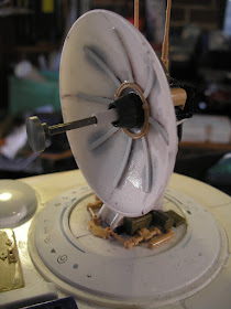
The communications dish sits in a well. The circular shape surrounding the well is the outer dial from a washing machine made from good quality ABS. The dish itself is made from another cut down battery powered push activated light. There are two sizes of these, this being the smaller one, the larger is the one cut in half on each side of the rear hull. These I find at the hardware store, the small ones come two to a pack and are much cheaper and more readily available than equivalent EMA elliptical vessel heads.


The dish will be position-able but not motorised.


The next task I started on was the side hatches.
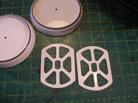
I bought some dummy ccd camera housings for the clear plastic domes (for another project) on ebay.
The bases for the domes were cut down and employed for the hatch surrounds. I needed a short tube to mate with the curved side of the hull. After much thought and not finding any pvc tube the right size a came up with a fabricated solution. I used this handy online tubing coping calculator to print out a paper pattern to cut some 1mm styrene sheet to the fish mouthed intersecting shape fitting the hull curve. You enter in the dimensions of the two intersecting tube sizes. the thickness of the cutting tube , in this case 1mm styrene and the angle here being 90 degrees. Basically I made two sine wave shapes which are each 180 degrees of the tube. First I cut a circle of 2mm styrene 2mm under size in diameter and then placed a central former with the arc of the hull cutaway. To this central spine I added various depth strips to match the curve. Then this structure was wrapped with the 1mm styrene sine shapes.  A sheet of coarse sandpaper was then wrapped around the hull curve and the whole inner structure sanded to suit. Although the black styrene makes it hard to see, it fits pretty well and only a tiny amount of filling will be required.


Once I had the surround sorted I drew up a suitable hatch shape in Draft Sight and printed it out full size. All the corner radiuses get a centre mark. This paper was glued with ordinary UHU stick glue onto two pieces of 2mm styrene stuck together with Scotch brand double sided tape as I needed two of them, one for each side. The center marks were first drilled out with a 2mm drill and then followed up by an 8mm step drill, all the rounded corners having a 4mm radius. Then I dug out the old scroll saw (the same one I used to make the aluminium chassis frames) and sawed between the holes finishing up with some filing and then rounding the front surface edges by scraping with a 150mm (6") metal ruler.


A further charity shop find, a strange pleasant sounds maker designed to help people go to sleep, is going to be a sensor dome on the hull at the front. This is just the top of it, the base having been removed.


More soon...

Part 1, Part 2, Part 3, Part 4, Part 5, Part 6, Part 7

Tuesday, 6 October 2015

Moon Bus part 2

Part 1

A couple of issues which bugged me about this project have now been addressed.
The first was the fact that the Integy wheel wideners/adaptors made the wheels stick out too far.
I wondered if it was possible to find 14mm hex free machining rod and sure enough there was some on Ebay so after obtaining a half meter length I set out to see if I could make my own 14mm hex hubs. Below is the result. In fact this is a reject where I mistakenly made the slot for the axle pin 1mm too deep.
The slot was done using a 2mm milling cutter held in the mini lathe chuck with the hex gripped in the tool post packed up to the correct center height using a 1.5mm scrap of aluminium sheet. The hex adapter's hole was lined up with the center of the chuck using a lathe center. The cross slide was moved 5.5mm out from center in both directions leaving an 11mm slot 2mm deep.


The rims are then secured using the long barrel nuts from the Integy adapters which previously were too short.  I had previously drilled out the rims to fit my wider diameter home made barrel nuts so I had to make 4 brass tube sleeves that fit over the integy barrel nuts to fit the wider diameter holes in the rims. The result is that the rims sit about 12mm closer to the axles and look and perform much better.

The other problem was that the location of the  curved shock mounts on the axle that I made interfered with the full turn of the steering. that was fixed by shortening the fuel tubing bushes, swapping the cap screws to a lower profile button head and dremeling out a clearance groove for the shock shaft in the mounts. Now I get full lock without binding the servo travel.


The picture above also shows the newly made hex in position and the new more cosy clearance for the steering arm.

Added to the suspension set up was a front and rear sway bar. This was possible because I swapped out the Venom Creeper transmission (which went into the ToyBash truck project) for an Axial SCX10 transmission which locates the motor along side. You can clearly see the slot which allows the sway bar to slide back and forth as the suspension compresses. The sway bars were made from bent 2mm piano wire.


An electronics tray was made from 2mm styrene, heated and bent in the middle to match the angle of the side frames. A flat raised section is added to support the battery and get over the top of the transmission which protrudes up through a shaped hole in the tray. A start has been made in laying out the electronics. A small clamping antenna tube holder made from some 10mmm pvc has been added on one of the 6mm rod cross members. There is a horizontal saw slot through which the m3 cap screw clamps down and a small vertical slot at the other end which allows for the pre-housed antenna wire to pass through before pushing the tube into the 3mm hole.


A start has been made on skinning the wooden hull frame with 1mm styrene. The wooden frame was sealed with shellac first which helps the thick super glue to go off quickly which is otherwise a problem for porous plywood end grain. I like shellac as it is easy to mix up the flakes with methylated spirits, it dries fast and is easily sandable, plus it is a reasonably natural material without lots of nasty chemicals of which there are more than enough in plastic model making.

The areas of the plastic sheet that were to come into contact with the superglue were marked out and then roughed up with very coarse sandpaper. It took a bit of coaxing with clamps and tie down straps to get it to conform to the radius required. It is impossible to handle trying to do glue it all at once so I glued it in stages with the occasional assistance of that foul smelling Zip Kicker (cyanoacrylate accelerant).  When doing this sort of thing it is wise to make the sheet bigger than needed all round and then trim the excess off after the glue has fully set.


The interior of the cockpit has also been skinned. The circular side windows are made from a PVC pipe reducer. It has a small lip on the inside against which an acrylic sheet disk window will sit. A ring of pvc pipe that fits the inner diameter will then slide in from the outside securing the window neatly in place. I plan to put a couple more porthole windows down the side.
The 1mm styrene sheet still has the clear plastic film protective sheet on it which is why it looks bit ragged in places. I will leave that on as long as possible to stop the surface getting unduly scratched while I work on it.


The rear has a cut in half push light housing glued on. There is a rear door structure still to be built and added.


A 1/16 Bruder man squats in the approximate position he will occupy. He originally had a co-driver to keep him company  but he was requisitioned for the Toy bash truck. I have a replacement coming and to mix it up a bit and redress the gender bias I am thinking it is going to be a Bruder female figure.

This project shares much in common with the ToyBash project having 4 wheel steering and sharing similar components in the drive train.They are also both in the same scale, the idea is that they would exist in the same world and time-frame.

Part 1, Part 2, Part 3, Part 4, Part 5, Part 6, Part 7